Image capturing control apparatus, image capturing apparatus, image capturing system and image capturing control method

a control apparatus and image technology, applied in the field of image capture control apparatus, image capture apparatus, image capture system and image capture control method, can solve the problem of taking a long time for wave detection processing, and achieve the effect of high speed and highly accurate processing relating to image captur

Active Publication Date: 2018-08-16
SONY CORP
View PDF1 Cites 1 Cited by
  • Summary
  • Abstract
  • Description
  • Claims
  • Application Information

AI Technical Summary

Benefits of technology

[0042]As described above, according to the present technology, high speed or highly accurate processing relating to image capture can be achieved.
[0043]It should be noted that the effect described here is not necessarily limitative and may be any effect described in the present disclosure.

Problems solved by technology

In this manner, a plurality of exposures are performed, which takes a long time for the wave detection processing.

Method used


Image

  • Image capturing control apparatus, image capturing apparatus, image capturing system and image capturing control method
  • Image capturing control apparatus, image capturing apparatus, image capturing system and image capturing control method
  • Image capturing control apparatus, image capturing apparatus, image capturing system and image capturing control method

Examples


first embodiment

1) First Embodiment

[0079]FIG. 4 is a flow chart showing the AE processing by the control unit 40 and the image processing circuit 30.

[0080]The control unit 40 sets image capturing conditions, i.e., exposure conditions being different in the pixel line group A and the pixel line group B (Step 101). The exposure conditions are set by at least one of the above-described electronic shutter speed and the gain by the ADC 26. For convenience of description, the exposure condition set for the pixel line group A is referred to as a setting A, and the exposure condition set for the pixel line group B is referred to as a setting B.

[0081]The setting A is such that an initial exposure amount is lowest, and the setting B is such that an initial exposure amount is highest, and vice versa.

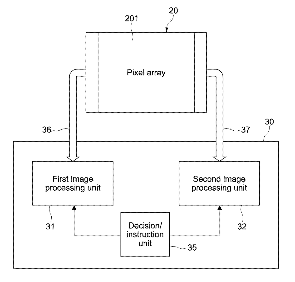
[0082]Next, the control unit 40 reads out the pixel signals from the pixel line group A and the pixel line group B in parallel via the first output path 36 and the second output path 37 (Step 102). In other words,...

second embodiment

2) Second Embodiment

[0097]FIG. 6 is a view for describing other processing example of the AE processing by the control unit 40 and the image processing unit as the second embodiment. Here, points different from the first embodiment will be mainly described, and the similar matters are omitted or described in a simplified way.

[0098]In the second embodiment, the control unit 40 performs the row thinning read-out from the predetermined pixel line group (first pixel line group) of the pixel line group A via the first output path 36 similar to the first embodiment.

[0099]On the other hand, the control unit 40 reads out a partial image unthinned at a partial area (partial pixel line) of a whole image generated at the pixel line group B via the second output path 37.

[0100]The partial image is at the following areas of the whole image generated at the pixel line group B. The areas are, for example, a center area, an upper end area, a lower end area, any area set by the user, or an area dynam...

third embodiment

3) Third Embodiment

[0106]Next, an example of the AF processing mainly by the image processing circuit 30 in the image capturing apparatus 100 will be described. FIG. 7 is a diagram for describing the AF processing.

[0107]In the third embodiment, in the control unit 40, the image read-out from the pixel line group A to the first image processing unit 31 via the first output path 36, and the image read-out from the pixel line group B to the second image processing unit 32 via the second output path 37 are thinned as in the first embodiment.

[0108]In the third embodiment, the setting A of the exposure condition at the pixel line group A and the setting B of the exposure condition at the pixel line group B may be same or different. The case when they are different will be described in sixth embodiment later.

[0109]In the third embodiment, the control unit 40 and the image processing circuit 30 perform the AF processing (for example, contrast AF processing). In the AF processing, the contro...


PUM


Abstract

An image capturing control apparatus includes a control unit and a plurality of image processing units. The control unit is configured to perform a read-out control of an image capturing unit such that image signals are read out in parallel, the image signals generated under different image capturing conditions for every pixel line group of a plurality of pixel lines of the image capturing unit. The plurality of image processing units are configured to process the image signals read out from the image capturing unit.

Description

CROSS REFERENCE TO RELATED APPLICATIONS[0001]This application is a U.S. National Phase of International Patent Application No. PCT / JP2015 / 001811 filed on Mar. 30, 2015, which claims priority benefit of Japanese Patent Application No. JP 2014-120014 filed in the Japan Patent Office on Jun. 10, 2014. The above-referenced applications is hereby incorporated herein by reference in its entirety.TECHNICAL FIELD[0002]The present technology relates to an image capturing control apparatus and an image capturing control method that control an image capture by an image capturing device, and to an image capturing apparatus and an image capturing system that include the image capturing control apparatus.BACKGROUND ART[0003]In general, in wave detection processing of AE (Automatic Exposure) processing, AF (Automatic Focus) processing, or the like of a camera, the camera gets an optimal exposed state and a focused state by a plurality of exposures. In this manner, a plurality of exposures are perf...

Claims


Application Information

Patent Timeline
Patent Type & Authority Applications(United States)
IPC IPC(8): H04N5/341H04N5/351H04N5/3745H04N5/378
CPCH04N5/341H04N5/378H04N5/3745H04N5/351H04N23/675H04N23/673H04N23/71H04N23/73H04N25/44H04N25/445H04N25/531H04N25/77H04N25/75H04N25/40H04N25/50
Inventor SAKANE, SEIJIRO
Owner SONY CORP
Why Eureka
Try Eureka