
High power-factor control circuit and power supply

Active Publication Date: 2016-03-24
BCD SEMICON MFG +1
View PDF6 Cites 19 Cited by
  • Summary
  • Abstract
  • Description
  • Claims
  • Application Information

AI Technical Summary

Benefits of technology

The present invention is about a new way to regulate power in a switch mode power supply (SMPS) that ensures a high power factor without the need for sampling of the input voltage. This is achieved by adjusting the power switch turn-on time based on the maximum peak current through the switch and a reference signal. The controller chip used can have as few as five pins and can select between boundary condition mode and discontinuous conduction mode. Overall, this new method helps to improve the efficiency and reliability of SMPS.

Problems solved by technology

The inventors have observed that conventional switched mode power supplies for driving LED lighting systems suffer from many limitations.
For example, conventional LED light bulbs often do not provide desirable efficiency in the utilization of the AC power as measured by “power factor.” Further, conventional techniques for improving the power factor often involves sampling of the line voltage.
Thus, the circuits is often complicated, and the performance of the power supply can be susceptible to the noise and instability of the line voltage.

Method used


Image

  • High power-factor control circuit and power supply
  • High power-factor control circuit and power supply
  • High power-factor control circuit and power supply

Examples


Embodiment Construction

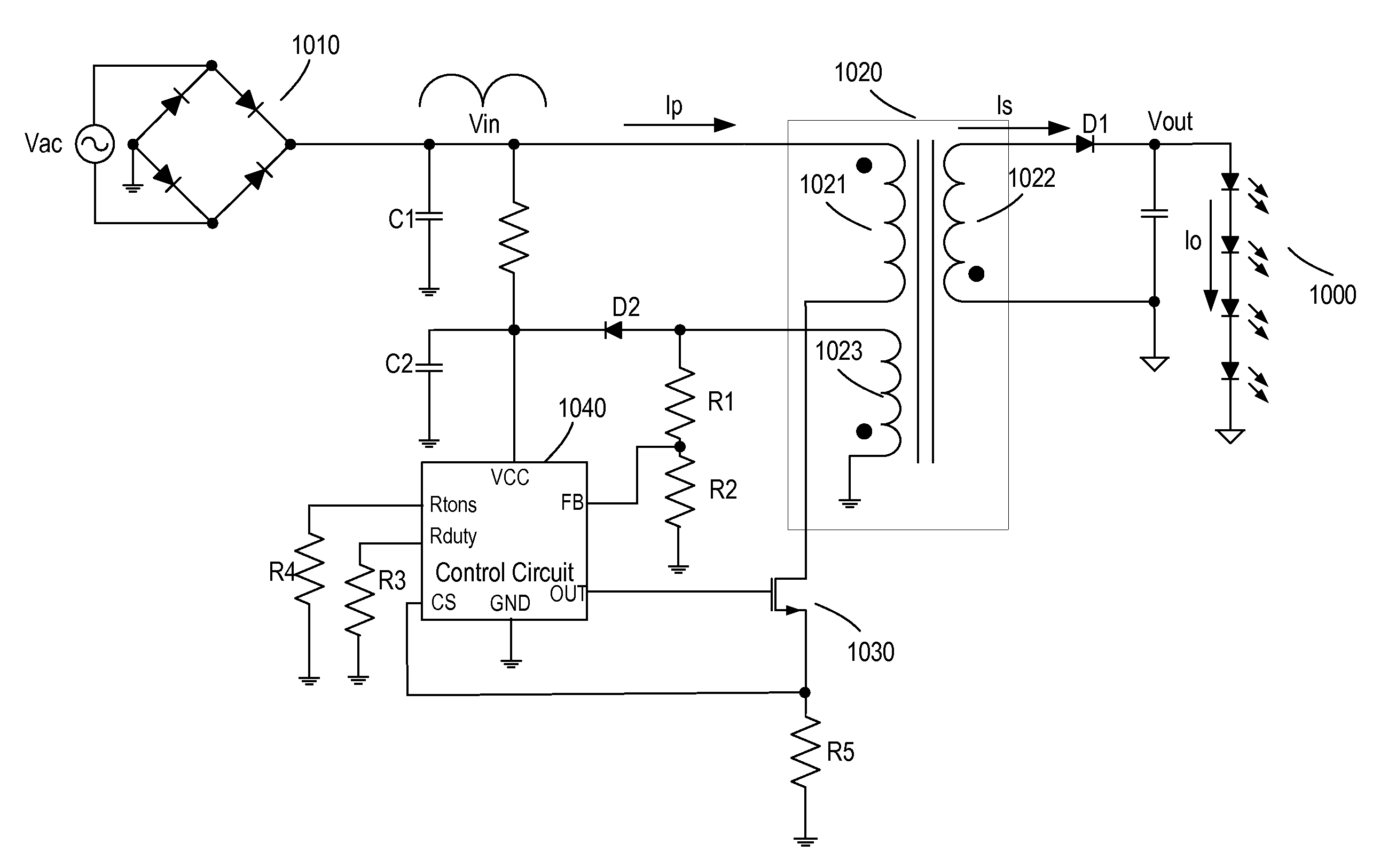
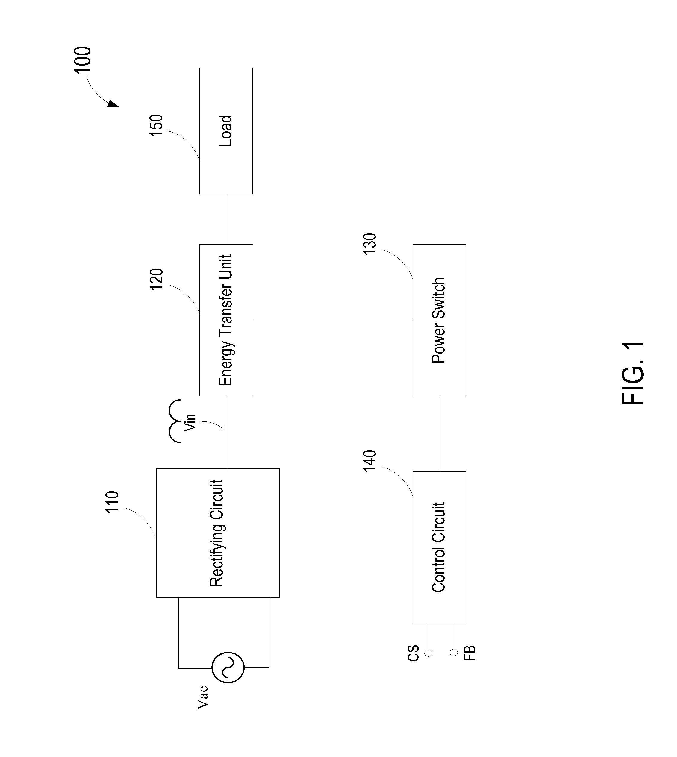
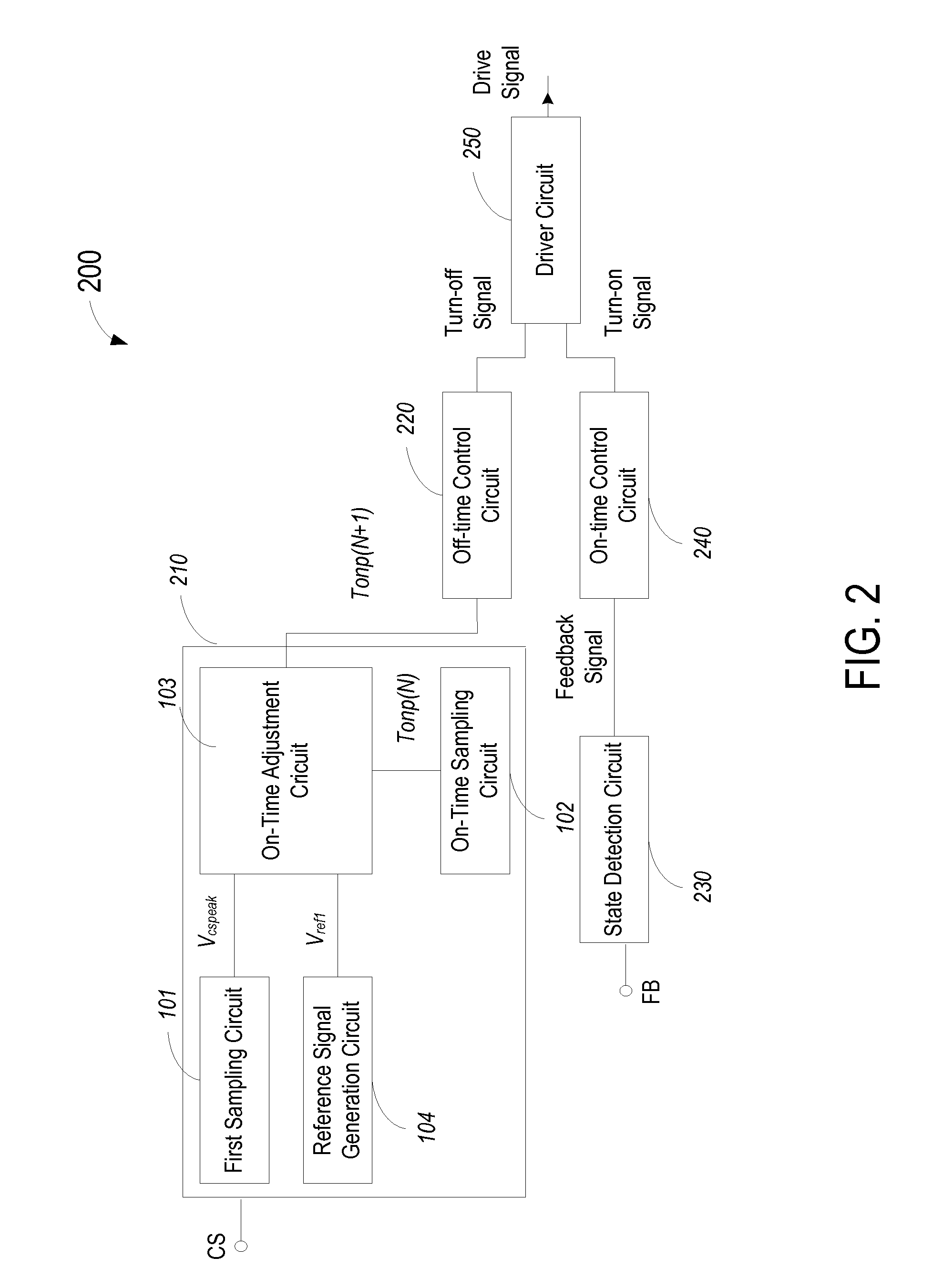
[0042]FIG. 1 is a simplified block diagram illustrating a switch mode power supply (SMPS) according to an embodiment of the present invention. As shown in FIG. 1, SMPS 100 includes a rectifier circuit 110, an energy transfer element 120, a power switch 130, and a power switch control circuit 140. Rectifier circuit 110 is configured for receiving an AC voltage Vac, and for providing a periodic rectified line voltage Vin, that is in phase with the input AC voltage Vac. Energy transfer element 120 is coupled to rectifying circuit 110 and an output load 100. Power switch 130 is coupled to an input of the energy transfer element. Power switch control circuit 140 controls the energy transfer element by controlling the on and off of the power switch based on information from at least two inputs, CS and FB. CS is information related to current flow in the power switch and the energy transfer unit, and FB is information related to the output of the power supply. In some embodiments of the in...


PUM


Abstract

An SMPS received a rectified periodic input line voltage and is configure to provide a regulated output. A power switch has a constant turn-on time in a given cycle of the rectified periodic input line voltage. A maximum value of the envelope of peak currents through the power switch is determined and is compared with a reference value, and the power switch turn-on time in the next cycle is adjusted accordingly. The output of the power supply is regulated to a target output value, and the current is in phase with the periodic input line voltage, resulting in a high power factor. No sampling of the line voltage is needed to maintain the high power factor. A controller chip can have as few as five pins. Alternatively, a seven-pin controller chip can have two external resistors for selecting operations in either Boundary Conduction Mode (BCM) or Discontinuous Conduction Mode (DCM).

Description

CROSS-REFERENCES TO RELATED APPLICATIONS[0001]This application is related to Chinese patent application No. 201310273298.9, filed on Jul. 2, 2013, and published on Oct. 2, 2013 as Chinese patent publication No. CN103337943A, by the same inventors and having substantially the same content as the present application, which is commonly owned and incorporated by reference herein in its entirety.BACKGROUND OF THE INVENTION[0002]The present invention relates generally to the field of switch mode power supply (SMPS). More particularly, embodiments of the present invention relate to SMPS for providing a constant output current for light emitting diode (LED) lighting applications.[0003]Switch mode power supply (SMPS) systems have many advantages over convention linear regulated power supplies. These advantages include smaller volume, better stability, and higher power efficiency. As a result, SMPS has found wide spread applications, such as televisions, set-top boxes, and video recorders, po...

Claims


Application Information

Patent Timeline
IPC IPC(8): H02M1/42H02M3/335
CPCH02M3/33507H02M1/4208H02M1/4258H05B45/375H05B45/385H02M1/0003H02M1/4291Y02B70/10
Inventor LIU, NACHEN, ZEQIANGZHU, YAJIANGDUAN, JIANHUADENG, CHAOHU, ZHIMINXU, SIYUAN
Owner BCD SEMICON MFG
Features
  • Generate Ideas
  • Intellectual Property
  • Life Sciences
  • Materials
  • Tech Scout
  • Unparalleled Data Quality
  • Higher Quality Content
  • 60% Fewer Hallucinations
Learn More