
Quick initialization of data regions in a distributed storage system

a distributed storage system and data region technology, applied in the field of buffering and data replication, can solve the problems of not being able to install such expensive storage devices in every node, poor performance of such operations, and being costly given the typical capacity requirements

Active Publication Date: 2016-03-31
IBM CORP
View PDF13 Cites 12 Cited by
  • Summary
  • Abstract
  • Description
  • Claims
  • Application Information

AI Technical Summary

Benefits of technology

This patent is about a method for quickly initializing a distributed file system by flushing write transactions and replicating certain parts of the file system. The method involves determining if the write transaction is the first one for a particular block of the file system and then flushing it to a recovery log. This log is then used to recover the data associated with the write transaction in case of failure. The method also includes appending the data to the recovery log and recording the byte ranges that need to be set a particular bit pattern. The entire block of the file system is then marked as committed. Overall, this method improves the speed and reliability of a distributed file system.

Problems solved by technology

Storage controllers typically use non-volatile read and write memory (NVRAM) to buffer these small writes and reduce their latency, but many systems, for example, systems based on a software-defined storage architecture, cannot install such expensive storage devices in every node.
This is a particular problem for spinning disk-only based systems because of their poor performance for such operations.
While storing data on large numbers of solid-state drives (SSDs) in every server can improve the situation, it is very costly given the typical capacity requirements in modern data centers.
In addition, naively using SSDs to buffer random writes can severely degrade the lifetime of SSDs.

Method used


Image

  • Quick initialization of data regions in a distributed storage system
  • Quick initialization of data regions in a distributed storage system
  • Quick initialization of data regions in a distributed storage system

Examples


Embodiment Construction

[0012]Aspects of the present invention are described below with reference to flowchart illustrations and / or block diagrams of methods, apparatus (systems), and computer program products, according to embodiments of the invention. It will be understood that each block of the flowchart illustrations and / or block diagrams, and combinations of blocks in the flowchart illustrations and / or block diagrams, can be implemented by computer program instructions. These computer program instructions may be provided to a processor of a general purpose computer, special purpose computer, or other programmable data processing apparatus to produce a machine, such that the instructions, which execute via the processor of the computer or other programmable data processing apparatus, create means for implementing the functions / acts specified in the flowchart and / or block diagram block or blocks.

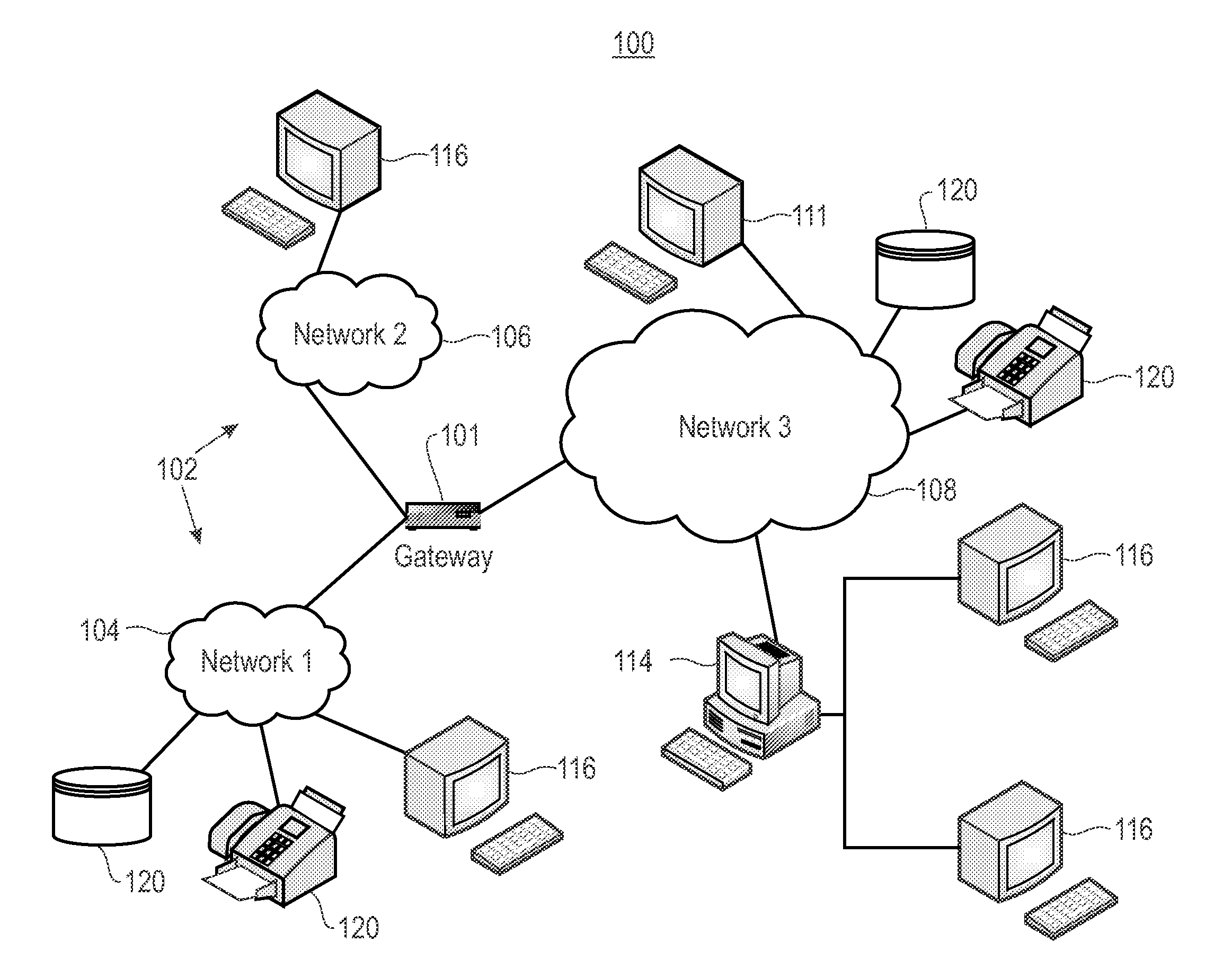
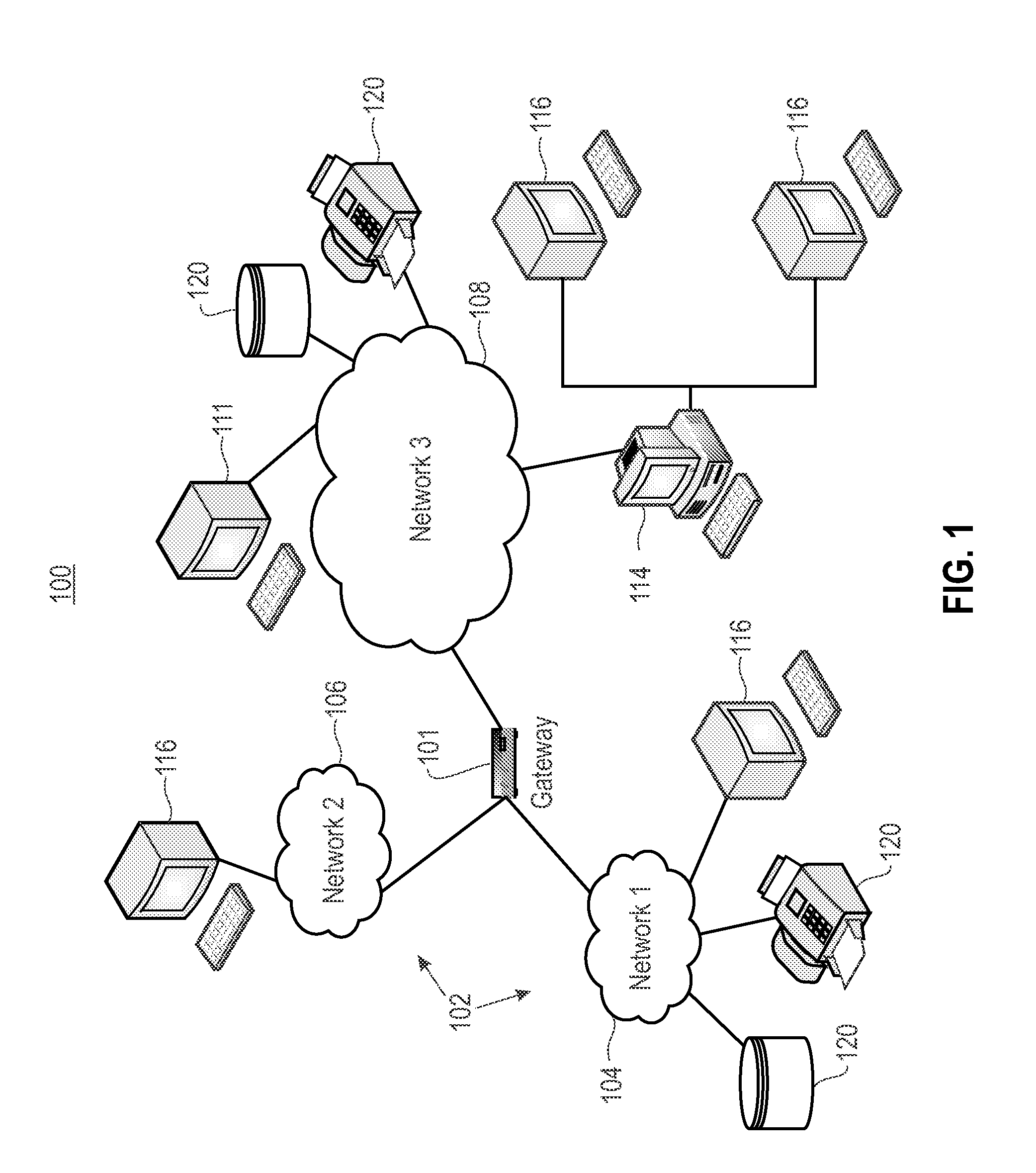
[0013]FIG. 1 illustrates a network architecture 100, in accordance with one embodiment. As shown in FIG. 1, a...


PUM


Abstract

A method includes flushing a write transaction based on byte-ranges within a file system block. It is determined if the write transaction is a first write transaction to the file system block and whether to flush the received write transaction to a recovery log. If it is determined to flush the write transaction to the recovery log and the received write transaction is the first write transaction: the data associated with the write transaction is appended in the recovery log and byte-ranges remaining in the file system block are recorded, and also recording an associated particular bit value or particular bit pattern that the remaining byte-ranges must be set to before the remaining byte-ranges are accessed or when a recovery sequence for recovering data in the recovery log executes due to failure. The write transaction is replicated. The entire file system block byte-range is marked as committed.

Description

BACKGROUND[0001]Embodiments of the invention relate to buffering and data replication and, in particular, quick initialization using buffering and replicating particular regions in a distributed file system.[0002]Numerous workloads, such as virtual machines (VMs), databases, and accesses to user home directories, send small and synchronous write operations to storage. In addition, many small writes to a file system actually translate into many more small writes to the storage layer to update the recovery log and various metadata structures. Storage controllers typically use non-volatile read and write memory (NVRAM) to buffer these small writes and reduce their latency, but many systems, for example, systems based on a software-defined storage architecture, cannot install such expensive storage devices in every node. This is a particular problem for spinning disk-only based systems because of their poor performance for such operations. While storing data on large numbers of solid-st...

Claims


Application Information

Patent Timeline
Patent Type & Authority Applications(United States)
IPC IPC(8): G06F17/30
CPCG06F17/30215G06F16/1844G06Q10/00
Inventor HILDEBRAND, DEANSCHMUCK, FRANK, B.
Owner IBM CORP
Learn More