
Light control monitoring system

a monitoring system and light control technology, applied in the direction of electrical equipment, electrical variable regulation, instruments, etc., can solve the problem of not offering an efficient power saving scheme, and achieve the effect of reducing power usage and maintenance costs, constant lumen output, and reducing power usage of connected loads

Inactive Publication Date: 2016-03-31
NORTH SENSOR
View PDF4 Cites 20 Cited by
  • Summary
  • Abstract
  • Description
  • Claims
  • Application Information

AI Technical Summary

Benefits of technology

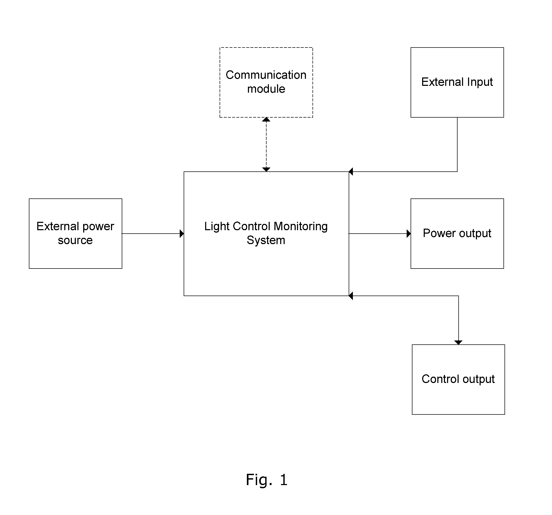
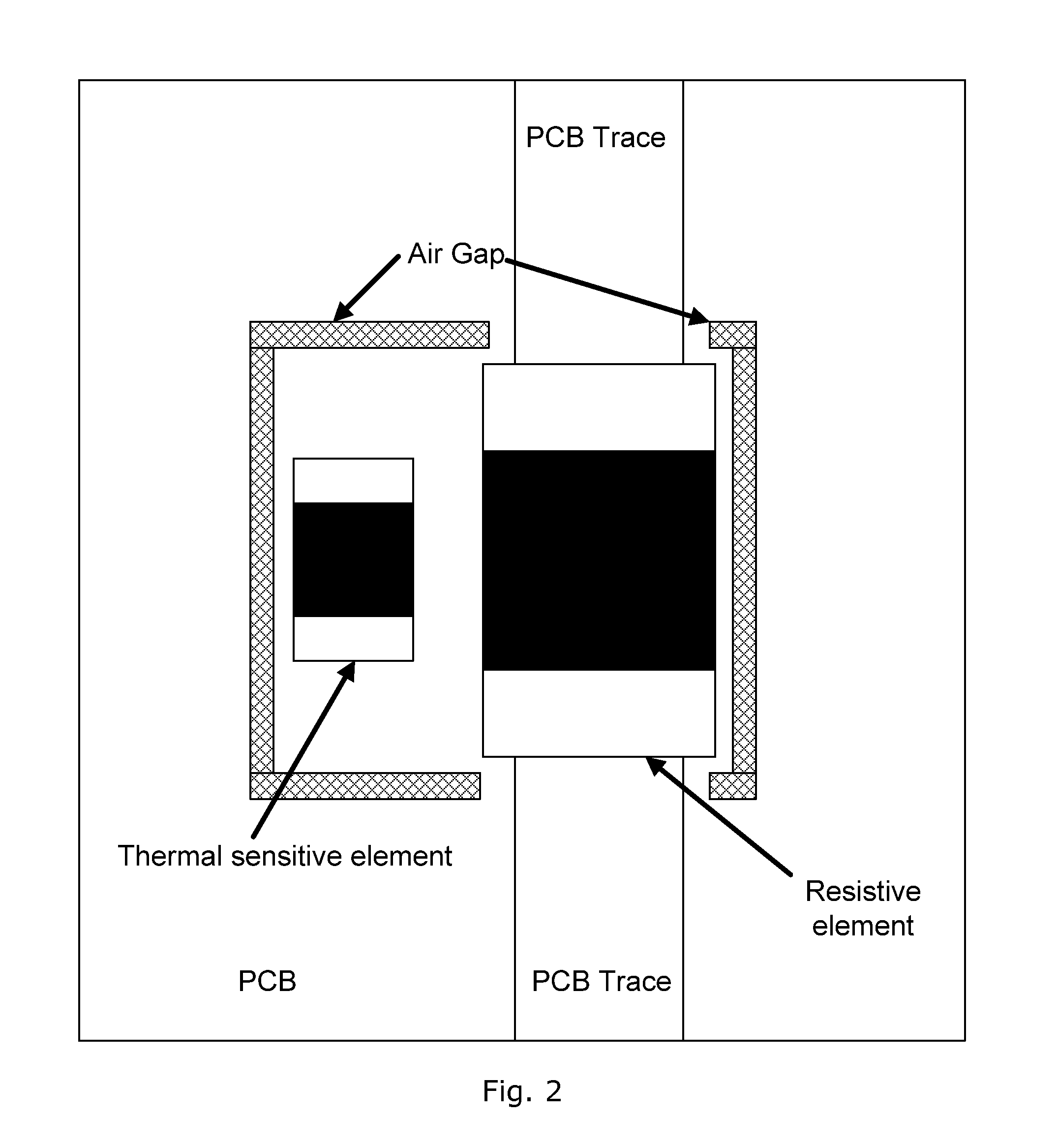
The present invention is about a control unit that can reduce power usage and maintenance cost by controlling a dimmable LED luminaire. The control unit uses sensor inputs to dynamically adjust the power output and can ensure constant lumen output. It also includes a method for measuring current consumption using a low-cost mechanism and a method to handle retransmissions and unresponsive nodes in a network. The control unit can identify the time and date by using a twilight switch, external signal, or power on / off times, which can be useful for reducing power delivery to the load connected to the control unit even without a power source.

Problems solved by technology

Thus, having a network of street lights the method and arrangement suggested in GB 2 457 971 do not offer an efficient power saving scheme during dusk / dawn hours.

Method used


Image

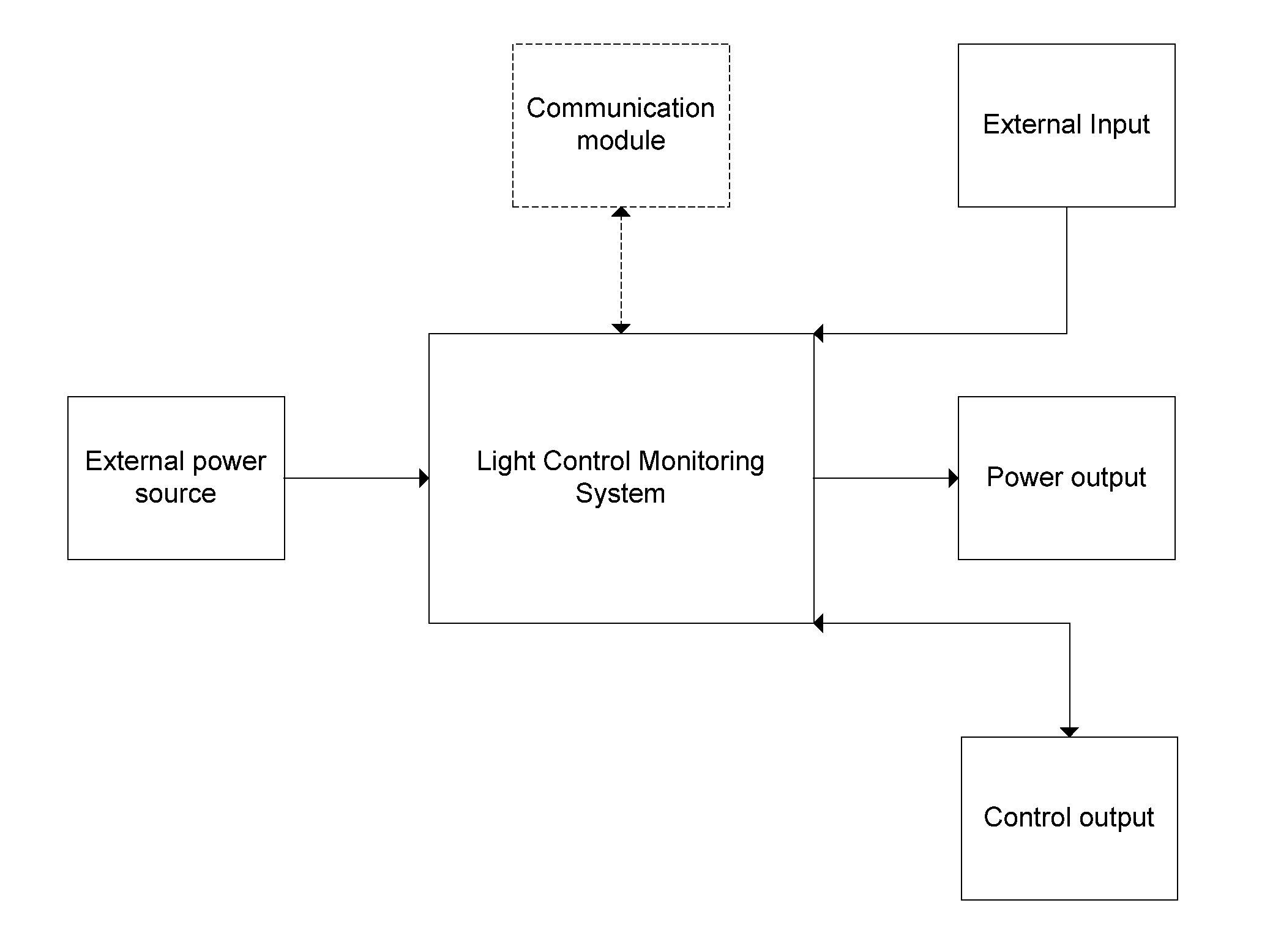
  • Light control monitoring system
  • Light control monitoring system
  • Light control monitoring system

Examples


Embodiment Construction

[0008]The above-mentioned objects are complied with by providing, in a first aspect, a method for operating a light source order to reduce power usage, the method comprising the steps of[0009]determining a predetermined traffic related activity, and[0010]operating the light source in accordance with said determined traffic related activity.

[0011]A traffic related activity may be any activity relating to traffic at or near the position of the light source, such as density of vehicles, number of pedestrians, number of cyclists etc. Also, a traffic related activity may be an indirect measure for the before-mentioned density, such as a total amount of light emitted from vehicles being at or near the location of the light source.

[0012]In order to save power the light intensity of the light source may be varied in accordance with the determined traffic related activity. Thus, the more background illumination from for example vehicles the less light is to be generated by the light source.

[...


PUM


Abstract

The present invention relates to a street light comprising means for determining a traffic related activity and control means for operating the street light according to the determined traffic related activity. A corresponding method for operating a street light is also disclosed.

Description

FIELD OF THE INVENTION[0001]The present invention relates to a Light Control Monitoring System (LCMS) for operating a light source. More specifically, the present invention relates to a control scheme that may be applied in street lights in order to save power. The invention further relates to a street light being capable of being operated in accordance with said control scheme.BACKGROUND OF THE INVENTION[0002]Various types of controllable street lights and associated methods have been suggested over the years.[0003]One approach is suggested in GB 2 457 971 where a LED-based street light is controlled during dusk / dawn hours by increasing / decreasing the light level of the street light.[0004]It appears that only control of a single and isolated street light is disclosed in GB 2 457 971. Thus, having a network of street lights the method and arrangement suggested in GB 2 457 971 do not offer an efficient power saving scheme during dusk / dawn hours.[0005]Moreover, light intensity control...

Claims


Application Information

Patent Timeline
Patent Type & Authority Applications(United States)
IPC IPC(8): H05B44/00H05B37/02
CPCH05B33/0854H05B37/0272H05B37/0227H05B47/11H05B47/105H05B47/19Y02B20/40H05B47/115H05B45/10
Inventor BJORN, LARS, NORGAARDSTAERK, DANAAROE, KASPAR, RAAHEDEJAKOBSEN, MIKKEL, AUNSBJERG
Owner NORTH SENSOR
Learn More