Unlock instant, AI-driven research and patent intelligence for your innovation.

Power recovery system for a vehicle

a technology for power recovery and vehicles, applied in vehicle heating/cooling devices, transportation and packaging, railway components, etc., can solve the problems of increasing the cost of the power recovery system, reducing the net benefit of the electrical power generated by the thermoelectric device, and difficulty in maintaining the temperature potential

Active Publication Date: 2016-04-07
NISSAN MOTOR CO LTD
View PDF9 Cites 4 Cited by
  • Summary
  • Abstract
  • Description
  • Claims
  • Application Information

AI Technical Summary

Benefits of technology

The present invention is a power recovery system for a vehicle's heating, ventilation, and air conditioning system. It uses a thermoelectric device to convert temperature differences between a heater core and a heat sink into electrical power. This recovered power can be used to operate various components of the vehicle's system, such as the air conditioning system or the rear window defrosting system. The system is efficient and cost-effective, and can provide a significant improvement in energy utilization in vehicles.

Problems solved by technology

The stability of the temperature potential in a vehicle is often insufficient, such that maintaining the temperature potential is difficult.
However, electrical power is required to operate the additional devices to maintain the temperature potential, thereby diminishing the net benefit of the electrical power generated by the thermoelectric device.
Furthermore, installing the additional devices to facilitate maintaining the temperature potential increases the expense of the power recovery system.

Method used


Image

  • Power recovery system for a vehicle
  • Power recovery system for a vehicle
  • Power recovery system for a vehicle

Examples


Embodiment Construction

[0015]Selected exemplary embodiments will now be explained with reference to the drawings. It will be apparent to those skilled in the art from this disclosure that the following descriptions of the exemplary embodiments are provided for illustration only and not for the purpose of limiting the invention as defined by the appended claims and their equivalents.

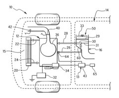
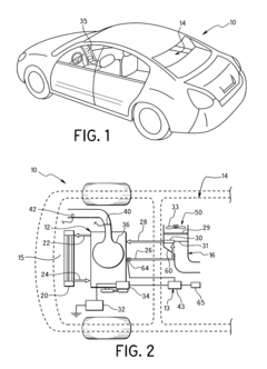
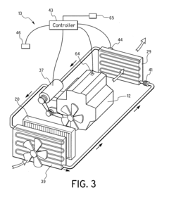
[0016]A power recovery system 67 for a heating, ventilation and air conditioning system of a vehicle includes a heater core 30, a heat sink 61 and a thermoelectric device 63, as shown in FIGS. 4 and 5. The heater core 30 is disposed in a first flow path 71 in fluid communication with an air handling system flow path 77. The heat sink 61 is disposed in a second flow path 72 in fluid communication with the air handling system flow path 77. A cooling circuit supplies a cooling fluid to the heat sink 61 through the second flow path 72. The thermoelectric device 63 has a first surface 68 in thermal contact with the heater core 30, a...


PUM


Abstract

A power recovery system for a heating, ventilation and air conditioning system of a vehicle includes an air handling system flow path, and a heater core disposed in a first flow path in fluid communication with the air handling system flow path. A heat sink is disposed in a second flow path in fluid communication with the air handling system flow path. A cooling circuit supplies a cooling fluid to the heat sink through the second flow path. A thermoelectric device has a first surface in thermal contact with the heater core and a second surface in thermal contact with the heat sink. The thermoelectric device converts a temperature difference between the first and second surfaces to electrical power.

Description

BACKGROUND[0001]1. Field of the Invention[0002]The present invention generally relates to a power recovery system for a vehicle. More specifically, the present invention relates to a power recovery system for a heating, ventilation and air conditioning system of a vehicle. Background Information[0003]A power recovery system in a vehicle can include a thermoelectric device to generate electrical power through a temperature potential between opposing sides of the thermoelectric device. To efficiently generate electrical power, a large temperature potential is required. The stability of the temperature potential in a vehicle is often insufficient, such that maintaining the temperature potential is difficult. Additional pumps and fans may be used to avoid degradation of the temperature potential. However, electrical power is required to operate the additional devices to maintain the temperature potential, thereby diminishing the net benefit of the electrical power generated by the therm...

Claims


Application Information

Patent Timeline
Patent Type & Authority Applications(United States)
IPC IPC(8): B60H1/00
CPCB60H1/00007B60H1/00428B60H2001/00178B60H2001/2275Y02T10/88
Inventor EISENHOUR, RONALD
Owner NISSAN MOTOR CO LTD