Method for controlling battery of mild hybrid vehicle

a hybrid vehicle and battery technology, applied in the direction of battery/fuel cell control arrangement, process and machine control, instruments, etc., can solve the problems of increasing fuel consumption, insufficient use of stop and go function in heavy traffic congestion, etc., to prevent fuel consumption and improve fuel economy.

Active Publication Date: 2016-04-07
HL MANDO CORP
View PDF6 Cites 10 Cited by
  • Summary
  • Abstract
  • Description
  • Claims
  • Application Information

AI Technical Summary

Benefits of technology

[0019]The methods for controlling the battery of a mild hybrid vehicle, according to the embodiments of the present invention, can adjust a target SOC of an energy storage device on the basis of traffic conditions detected based on the driving state of a vehicle in order to prevent fuel consumption caused by unnecessary engine power generation, thereby improving fuel economy.

Problems solved by technology

However, the control method in the related art does not consider road / traffic conditions and accordingly, does not maximize a Stop and Go function that has a great effect of fuel economy improvement and a regenerative energy use function.
For example, in cases where the battery charging state is maintained to be a single target SOC, the Stop and Go function cannot be sufficiently utilized in heavy traffic congestion.
In contrast, maximum regenerative energy has to be used in road / traffic conditions that have a large regenerative quantity, but unnecessary engine power generation occurs in order to manage the battery, thereby increasing fuel consumption.

Method used


Image

  • Method for controlling battery of mild hybrid vehicle
  • Method for controlling battery of mild hybrid vehicle
  • Method for controlling battery of mild hybrid vehicle

Examples


first embodiment

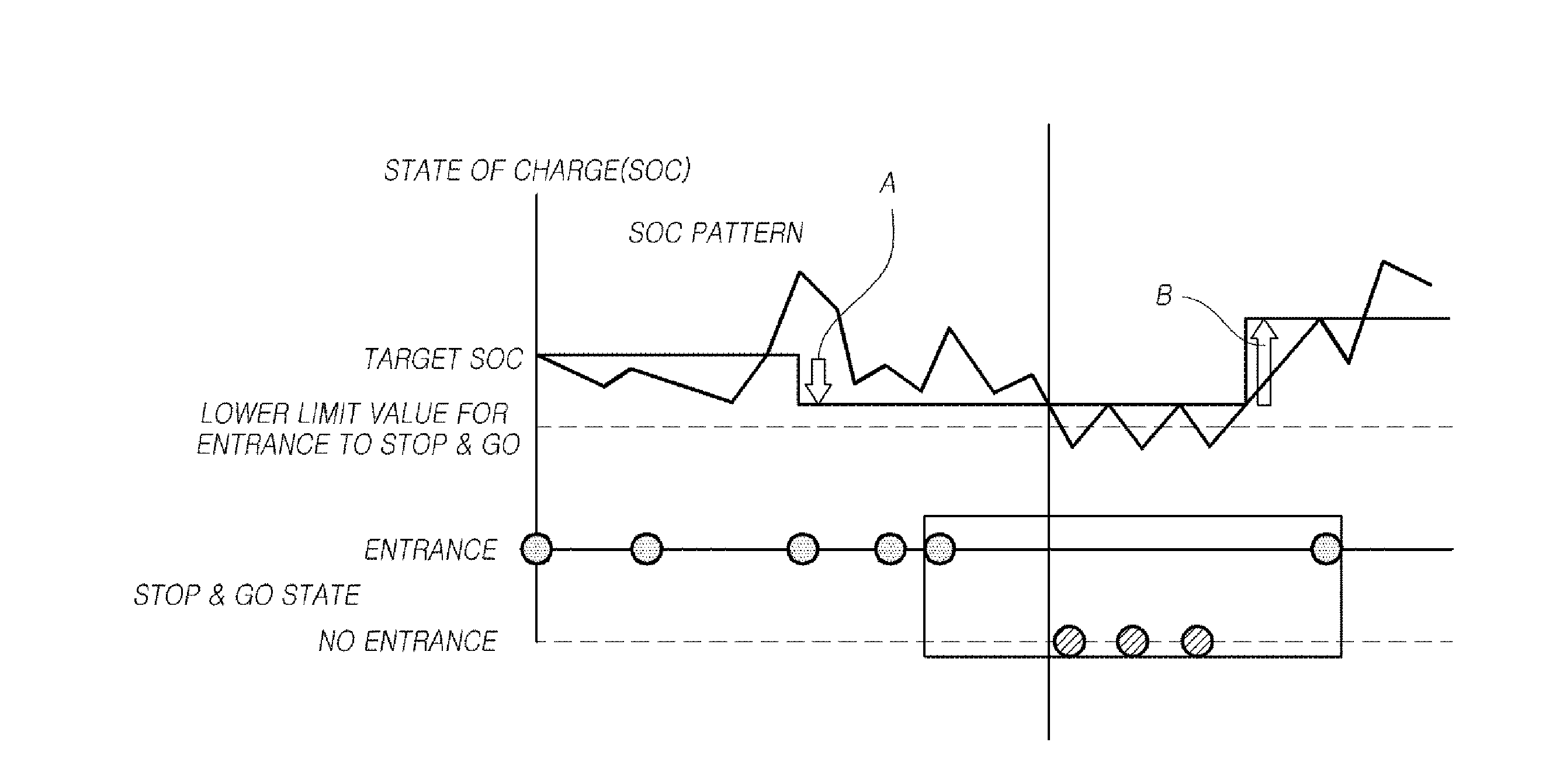
[0046]The step 1-1 (S110) and the step 1-2 (S120) of the method for controlling the battery of a mild hybrid vehicle, according to the present invention, will be described with reference to FIG. 6. As illustrated in FIG. 6, the first range of interest is set based on the number of times that the vehicle stops; namely, based on the number of times that the condition for an entrance to Stop and Go occurs. For example, as illustrated in FIG. 6, the first range of interest is set based on the assumption that the number of times that an entrance to the Stop and Go can be made is five, and the number of times that the Stop and Go does not operate because the SOC of the energy storage device 400 is smaller than a Stop and Go lower limit value although the entrance to the Stop and Go is possible is counted. The first range of interest is set to move as illustrated in FIG. 6 every time the condition for an entrance to the Stop and Go occurs, thereby making it possible to continually perform ...

second embodiment

[0049]As illustrated in FIG. 7, the first step S100 in the method for controlling the battery of a mild hybrid vehicle, according to the present invention, may include step 1-3 (S130) of setting a second range of interest for detecting the trend of an SOC of the energy storage device 400 and may include step 1-4 (S140) of calculating the average of the SOC of the energy storage device 400.

[0050]The trend of the SOC of the energy storage device 400 may be represented as illustrated in FIG. 8, and the second range of interest, which is a detection range of the SOC trend of the energy storage device 400, is set as illustrated in FIG. 9. The second range of interest may be set based on a preset time. In addition, an SOC of the energy storage device 400 may be detected during a counting operation at a predetermined interval, and the second range of interest may also be set based on a count number. As with the first range of interest, the second range of interest may be set to move as ill...


PUM


Abstract

A method for controlling the battery of a mild hybrid vehicle, according to an embodiment of the present invention, includes: a first step of detecting the traffic conditions based on the driving state of the vehicle; and a second step of adjusting the target SOC of an energy storage device based on the detected traffic conditions.

Description

CROSS-REFERENCE TO RELATED APPLICATION[0001]This application claims priority from and the benefit under 35 U.S.C. §119(a) of Korean Patent Application No. 10-2014-0135309, filed on Oct. 7, 2014, which is hereby incorporated by reference for all purposes as if fully set forth herein.BACKGROUND OF THE INVENTION[0002]1. Field of the Invention[0003]The present invention relates to a method for controlling the battery of a mild hybrid vehicle and, more specifically, to a method for determining a target State of Charge (SOC) of an energy storage device of a mild hybrid vehicle based on traffic conditions.[0004]2. Description of the Prior Art[0005]Vehicle manufacturers have made an effort to improve fuel economy and develop eco-friendly vehicles in response to the increase of social interest in rising oil prices and the environment, and hybrid systems that regenerate and use the deceleration energy of vehicles have emerged in order to satisfy this demand.[0006]In the related art, in order ...

Claims


Application Information

Patent Timeline
Patent Type & Authority Applications(United States)
IPC IPC(8): B60W20/13B60L11/18B60W20/12
CPCB60W20/13B60L11/1862B60W20/12B60W20/00B60W2510/244B60W2510/246B60W2520/10B60W2540/10B60W2540/12B60W2710/244B60W10/06B60W10/08B60W10/26B60L58/13B60W2556/10Y02T10/62Y02T10/70B60K6/28H02J7/14
Inventor JANG, IN GYU
Owner HL MANDO CORP
Why Eureka
Try Eureka