Method, system and computer program product for producing a raised relief map from images of an object

a technology of object surface and raised relief, applied in image data processing, color television, instruments, etc., can solve the problems of algorithm only operating, algorithm cannot apply to such images, and the location of illumination sources is either unknown or difficult to model

Active Publication Date: 2016-04-07
BIOMERIEUX SA
View PDF7 Cites 15 Cited by
  • Summary
  • Abstract
  • Description
  • Claims
  • Application Information

AI Technical Summary

Benefits of technology

[0016]performing one or more sequences of minimization operations to minimize a difference function between the pixel values obtained from the set of images and pixel values calculated using said model function, each minimization operation being performed by allowing one of said model components to vary while the others remain unchanged;

Problems solved by technology

However, such an algorithm only operates if the illumination source is a point light source and if directions of illumination sources are known.
In the domain of biological analysis, for example, the illumination sources are not point light sources and the location of the illumination sources is either unknown or not easy to model.
Thus, the algorithm cannot be applied to such images.
Furthermore, no parameters related to the intensity of the illumination sources are taken into account in this algorithm.
Thus, during the reconstruction process, information regarding the properties of the surface of the object may be lacking or insufficient and lead to incorrect representation of the surface of the object.
As a result, such an algorithm is not always suitable for use in photometric stereo reconstruction of images taken in the domain of biological analysis or of any images taken with a fixed position camera and complex illumination conditions or unknown illumination directions.
However, such an algorithm only operates if the positions of illumination sources and / or normals of specific pixels of images are known.
In some situations, such information is either not available or difficult to obtain.
As a result, such an algorithm is not suitable for generating an accurate image of a surface of an object if illumination conditions are unknown, as is often the case in the domain of biological analysis.
In addition, approximations may lead to incorrect representation of the image of the surface of the object at the end of the image reconstruction process.

Method used


Image

  • Method, system and computer program product for producing a raised relief map from images of an object
  • Method, system and computer program product for producing a raised relief map from images of an object
  • Method, system and computer program product for producing a raised relief map from images of an object

Examples


first embodiment

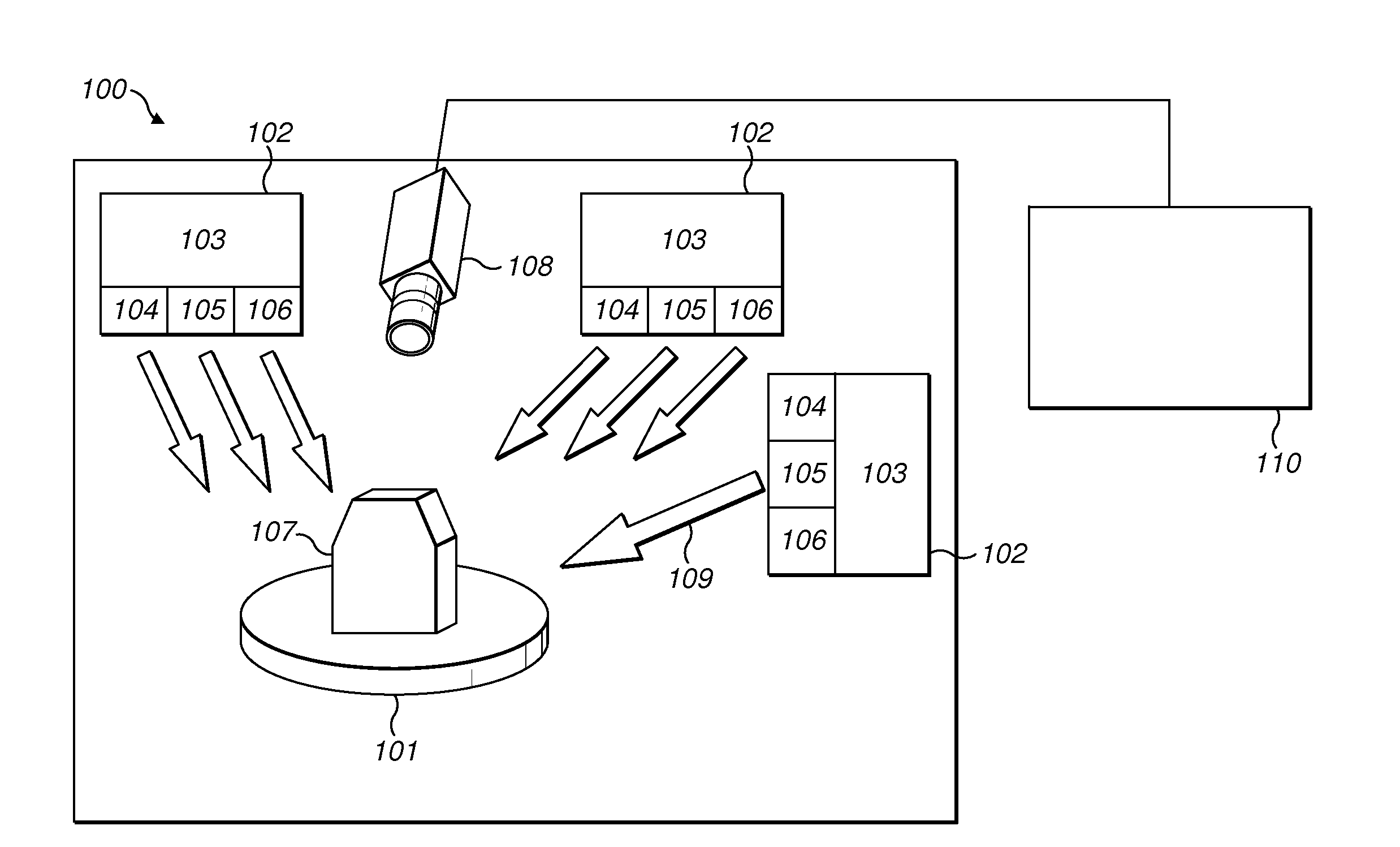
[0149]In a first embodiment, the intensity detection device 112 selects an initial image such as image 1. The intensity detection device 112 then selects a specific color channel, such as color channel R. The intensity detection device 112 detects the pixel value of each pixel in image 1 for color channel R. When considering specific examples of pixel 1 in image 1, the detected pixel values may refer to IR1(pixel1).

[0150]The intensity detection device 112 proceeds in the same manner with color channels G and B for image 1. In a similar manner, the detected pixel values may refer, for example, to IG1(pixel1) for color channel G and IB1(pixel 1) for color channel B.

[0151]The intensity detection device 112 then carries out the same steps for images 2 and 3. The intensity detection device 112 always selects corresponding pixels in all other initial images to determine the corresponding intensity of the same pixel in all the different initial images. It should be understood that the term...

second embodiment

[0231]In a second embodiment, the present invention provides a solution for considering value constraints and quality constraints for the photometric stereo model during execution of the optimization method.

[0232]In order to integrate value and quality restrictions for the photometric stereo components, the minimization functions for finding albedo values, light source intensities, light source directions and surface normals matrices take into account supplementary equality and inequality constraints. Minimization operations for each of the model components are described below.

[0233]In FIG. 5, the light source directions matrix including norm constraints should be found using the shown formula for V

subject to vk,x2+vk,y2+vk,z2=1

where k=1, . . . , ni, and vector (vk,x, vk,y, vk,z) corresponds to the lighting direction used during the acquisition of the kth image.

[0234]In order to obtain the surface normals matrix with value norm constraint and quality constraints, the minimization pr...


PUM


Abstract

A method for obtaining a model of an object surface from a plurality of images of said object, wherein the object is illuminated with one or more illumination sources, the method comprising: —obtaining a set of images each comprising an array of pixels and representing similar views of an object, wherein the similar views are obtained under different illumination conditions; —defining a model function that expresses the known pixel intensity values of the images in terms of the following unknown model components: —a first model component (A) representing the albedo of the object at each pixel location and being the same for the plurality of images and being an albedo value; —a second model component (L) representing an intensity of illumination for each image and being an illumination source intensity value being the same for all pixels of each image; —a third model component (V) representing a specific illumination direction and being different for each image and being an illumination vector and being the same for all pixels of each image; —a fourth model component (N) representing surface normal directions of the object surface at each pixel position and being the same for all images and being a normal vector; —performing one or more sequences of minimization operations to minimize a difference function between the pixel values obtained from the set of images and pixel values calculated using said model function, each minimization operation being performed by allowing one of said model components (A, L, V, N) to vary while the others remain unchanged; —outputting the fourth model component (N) as said model of the object surface.

Description

FIELD OF THE INVENTION[0001]The present invention relates to a method, system and computer program product for producing a raised relief map of the surface of an object from a plurality of images of the object.BACKGROUND OF THE INVENTION[0002]In the domain of image processing, the photometric stereo method is a well-known method for producing a raised relief map of the surface of an object. The photometric stereo method operates by using a plurality of images of an object taken with a camera in a fixed position, with one or more illumination sources providing different directions of illumination. The aim of the photometric stereo method is to provide a raised relief map of the surface of an object by applying a specific algorithm to data related to images being taken. In the domain of biological analysis, for example, the objects comprise micro-organisms. The raised relief maps of objects such as micro-organisms obtained using such a method allow several characteristics of the micro...

Claims


Application Information

Patent Timeline
Patent Type & Authority Applications(United States)
IPC IPC(8): G06T7/00G06T15/50H04N9/31
CPCG06T7/0073G06T15/506H04N9/315G06T2207/30024G06T7/586G06T5/50G06T2207/10024G06T2207/10152G06T3/4007G06T2207/20221G06T7/514G06T7/90
Inventor ALLANO, LORENEKYRGYZOVA, KHRYSTYNA
Owner BIOMERIEUX SA
Why Eureka
Try Eureka