Illumination device

a technology of endoscope and slit, which is applied in the field of slit device, can solve the problems of large increase in the tip diameter of the endoscop

Active Publication Date: 2016-04-14
OLYMPUS CORP
View PDF4 Cites 6 Cited by
  • Summary
  • Abstract
  • Description
  • Claims
  • Application Information

AI Technical Summary

Problems solved by technology

This requires a large installation space in the radial direction of the endoscope and thus results in a large increase in the tip diameter of the endoscope.

Method used


Image

  • Illumination device
  • Illumination device
  • Illumination device

Examples


first embodiment

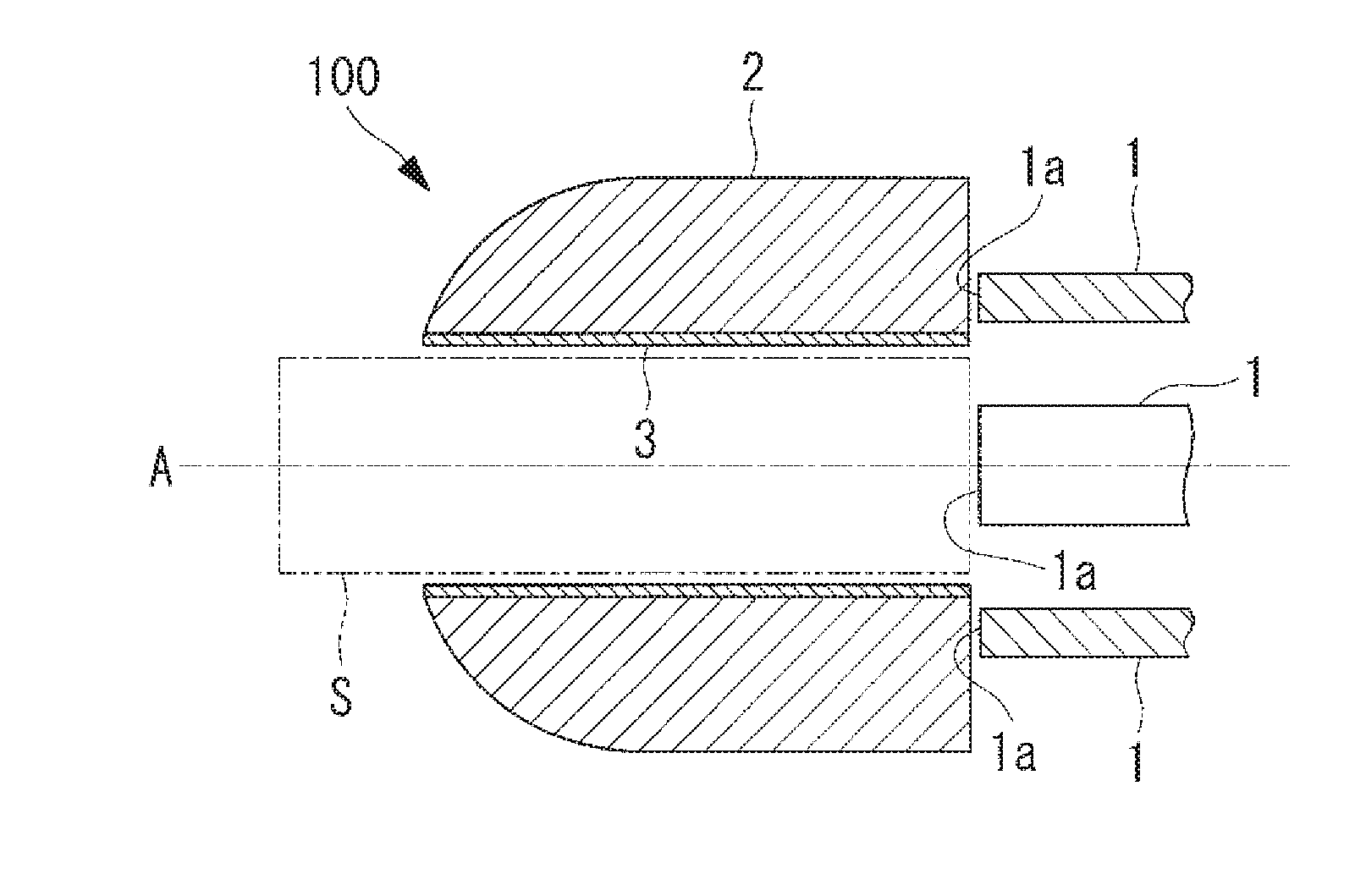
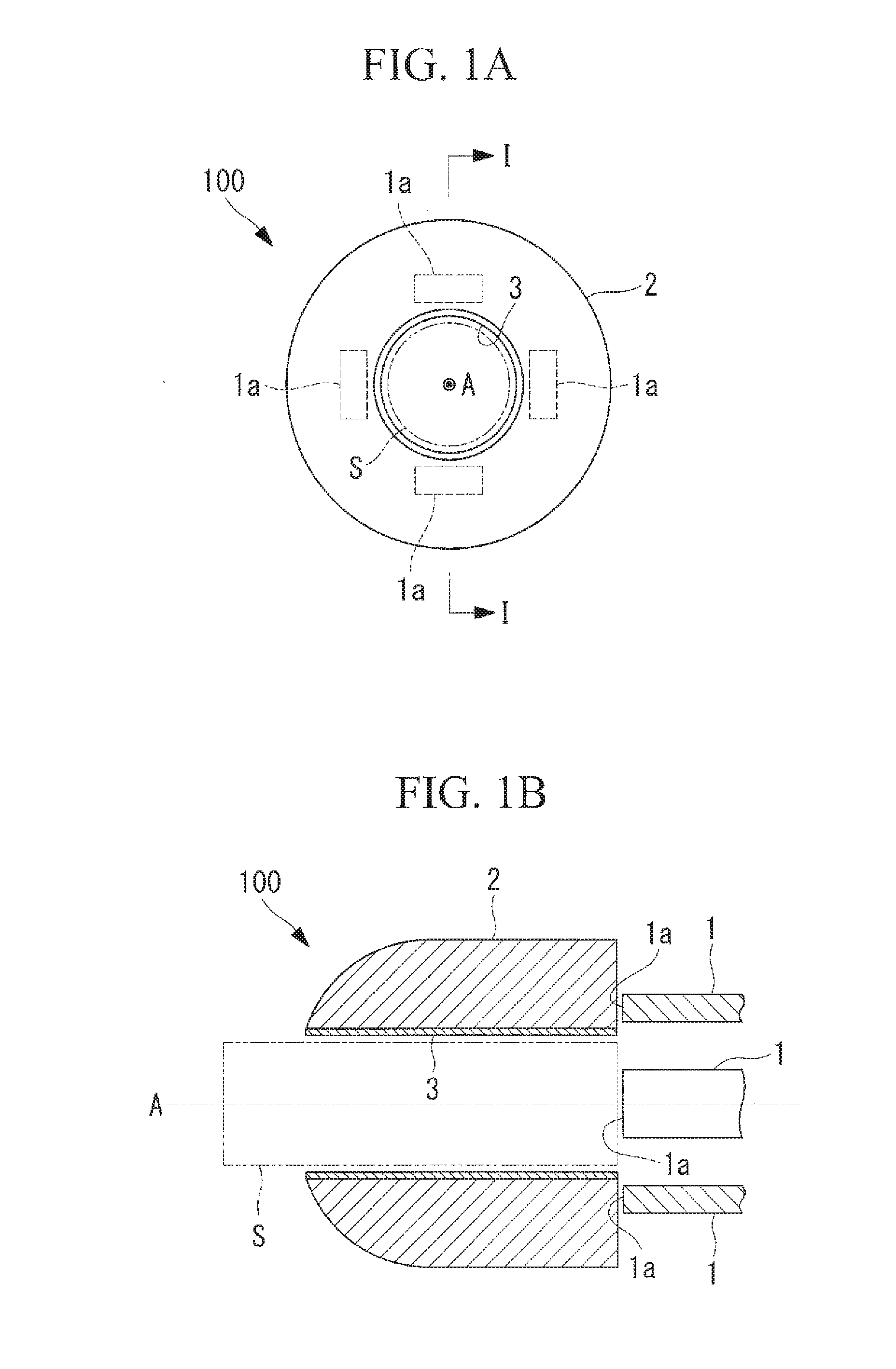
[0022]An illumination device 100 according to a first embodiment of the present invention will be described below with reference to FIGS. 1A to 5.

[0023]As shown in FIGS. 1A and 1B, the distal-end portion of the illumination device 100 according to this embodiment (i.e., a portion composed of a diffusion layer 2 and a reflective layer 3, described later) has a cylindrical structure and is exposed to the outside so as to circumferentially surround an image-capturing optical system provided at the distal end of an endoscope. In the same figures, the space S enclosed by the two-dot chain line represents the space were the image-capturing optical system is disposed, and the axis A represents the observation optical axis of the image-capturing optical system. In particular, the illumination device 100 according to this embodiment is designed for endoscopes including image-capturing optical systems having viewing, angles of 180° or more and capable of simultaneously capturing images of fie...

second embodiment

[0039]An illumination device 200 according to a second embodiment of the present invention will now be described with reference to FIGS. 6 and 7. In this embodiment, the elements that differ from those of the first embodiment described above are mainly described, whereas the same elements as in the first embodiment are labeled with the same reference signs and are not described.

[0040]As shown in FIG. 6, the illumination device 200 according to this embodiment differs from the illumination device 100 according to the first embodiment mainly in that the illumination device 200 includes a diffusion layer 21 having an approximately C-shaped transverse cross-section formed by removing a portion extending in the circumferential direction, rather than the diffusion layer 2 extending over the entire circumference thereof.

[0041]A cutout 21a formed by removing, in the longitudinal direction, a portion of the diffusion layer 21 extending in the circumferential direction has an annular-sector-s...

third embodiment

[0047]An illumination device 300 according to a third embodiment of the present invention will now be described with reference to FIGS. 8A to 9B. In this embodiment, the elements that differ from those of the first and second embodiments described above are mainly described, whereas the same elements as in the first and second embodiments are labeled with the same reference signs and are not described.

[0048]As shown in FIGS. 8A and 8B, the illumination device 300 according to this embodiment differs from the illumination devices 100 and 200 according to the first and second embodiments mainly in that the illumination device 300 includes a plurality of (in this example, four) diffusion layers 22 arranged substantially at regular intervals in the circumferential direction centered on the observation optical axis A, rather than the cylindrical diffusion layers 2 and 21, and that the illumination device 300 includes four units each composed of a diffusion layer 22, a reflective layer 32...


PUM


Abstract

An illumination device according to the present invention includes a light output unit having an output end that outputs illumination light; a diffusion layer that is disposed in a circumferential direction centered on a predetermined axis and that receives the illumination light from the output end, guides the illumination light while diffusing the illumination light, and outputs the illumination light from a surface thereof; and a reflective layer that is provided adjacent to a surface of the diffusion layer at an inner side in a radial direction and that reflects the illumination light outward in the radial direction. The diffusion layer contains a light guide material that guides the illumination light and a diffusion material dispersed and supported in the light guide material.

Description

CROSS-REFERENCE TO RELATED APPLICATIONS[0001]This is a continuation of International Application PCT / JP2014 / 066700, with an international filing date of Jun. 24, 2014, which is hereby incorporated by reference herein in its entirety. This application claims the benefit of Japanese Patent Application No. 2013-143679, filed on Jul. 9, 2013, the content of which is incorporated herein by reference.TECHNICAL FIELD[0002]The present invention relates to illumination devices, and particularly to an illumination device for use with endoscopes having viewing angles of 180° or more.BACKGROUND ART[0003]There is a known endoscope that has a wide viewing angle, i.e., 180° or more, and that allows simultaneous observation of forward, side, and even backward fields of view (see, for example, patent literature PTL 1 below). For example, if an endoscope having a viewing angle of 180° or more is used in the large intestine, where numerous folds are found, the back side of a fold can be observed witho...

Claims


Application Information

Patent Timeline
Patent Type & Authority Applications(United States)
IPC IPC(8): A61B1/06G02B23/24A61B1/00G02B5/02
CPCA61B1/0615G02B5/0242A61B1/00096A61B1/0623G02B23/2469G02B5/0205A61B1/0607G02B23/2423
Inventor FURUTA, KOICHIRO
Owner OLYMPUS CORP
Why Eureka
Try Eureka