
Steel cord for tire reinforcement

Inactive Publication Date: 2016-04-14
KISWIRE
View PDF12 Cites 3 Cited by
  • Summary
  • Abstract
  • Description
  • Claims
  • Application Information

AI Technical Summary

Benefits of technology

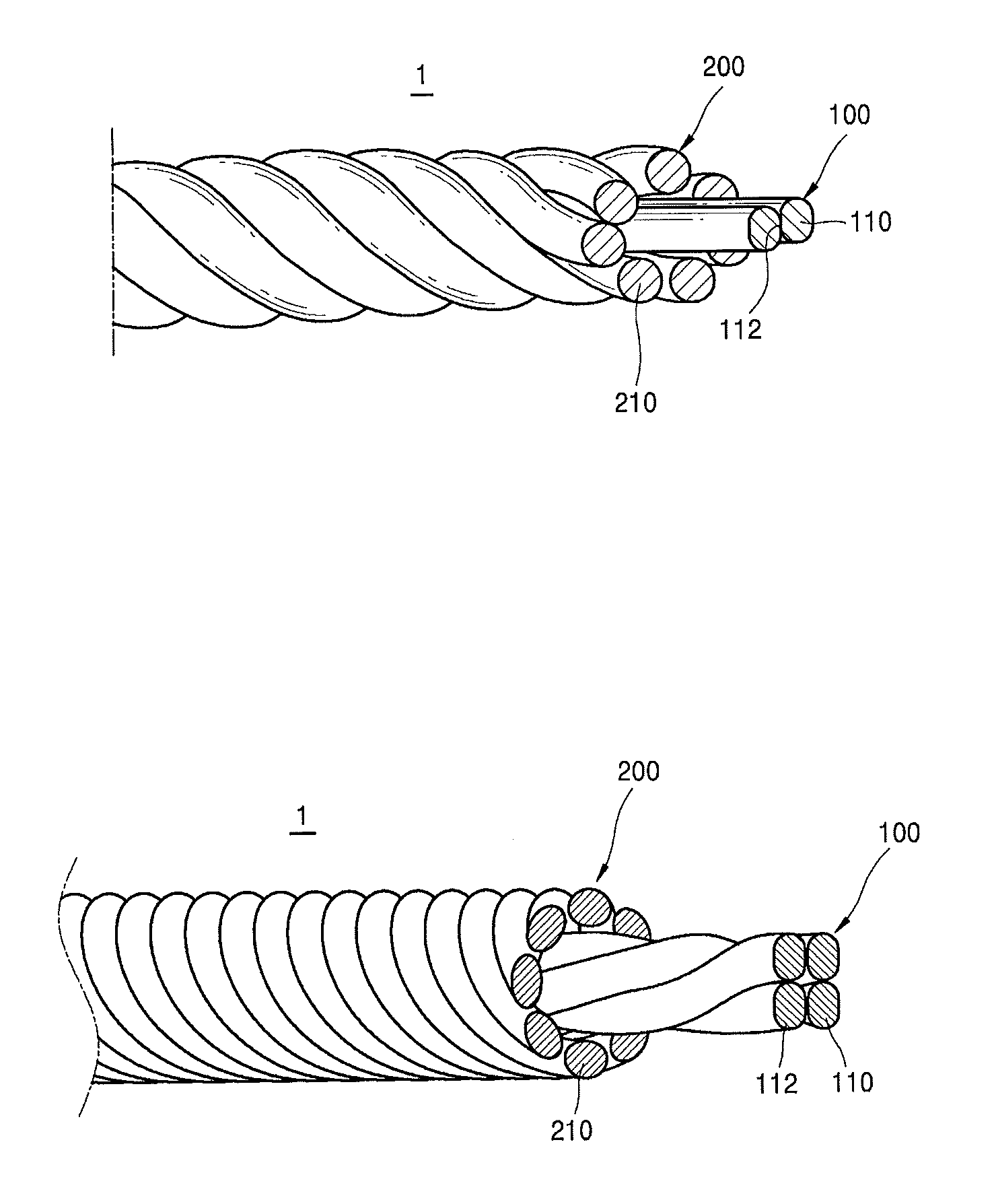
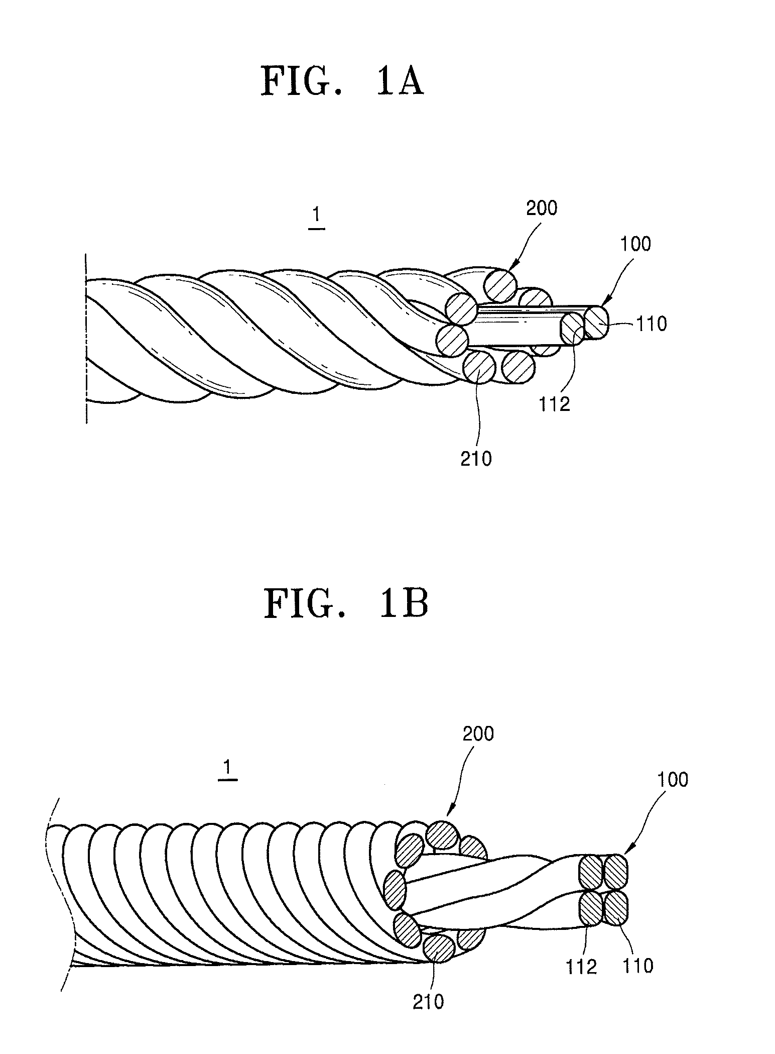
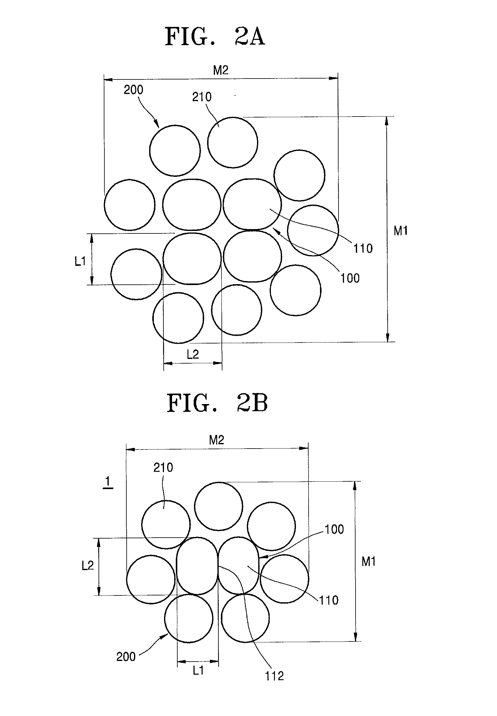
The patent describes a steel cord used to reinforce tires. The steel cord has flat surfaces between the wires, which improve fatigue resistance, rubber permeability, and prevent moisture and corrosion from spreading inside the cord. This increases the life span of the tire and improves productivity and user convenience.

Problems solved by technology

In an existing steel cord for a tire reinforcement having a strand structure (1×n), element wires forming the steel cord generally have a circular cross-section, and a contact between the element wires is a point contact or line contact, the element wires are likely to be damaged when friction between the element wires occurs.

Method used


Image

  • Steel cord for tire reinforcement
  • Steel cord for tire reinforcement
  • Steel cord for tire reinforcement

Examples


Embodiment Construction

[0031]Hereinafter, exemplary embodiments of the inventive concept will be described with reference to the accompanying drawings. The inventive concept may, however, be embodied in many different forms and should not be construed as being limited to the exemplary embodiments set forth herein; rather, these exemplary embodiments are provided so that this disclosure will be thorough and complete, and will fully convey the inventive concept to those of ordinary skill in the art. It should be understood, however, that there is no intent to limit the inventive concept to the particular forms disclosed, but on the contrary, the inventive concept is to cover all modifications, equivalents, and alternatives falling within the spirit and scope of the inventive concept. Expressions such as “at least one of” when preceding a list of elements, modify the entire list of elements and do not modify the individual elements of the list.

[0032]Spatially relative terms, such as “beneath,”“below,”“lower,...


PUM

PropertyMeasurementUnit
Diameteraaaaaaaaaa
Diameteraaaaaaaaaa
Tensile strengthaaaaaaaaaa

Abstract

A steel cord for a tire reinforcement having a non-circular cross-section includes: a lower strand; and an upper strand that surrounds an outer circumferential surface of the lower strand so as to have an m+n structure, wherein the lower strand includes a plurality of core wires, each of the plurality of core wires have a flat surface on a portion in which the plurality of the core wires come into contact with each other, and the plurality of core wires come into surface contact with each other through the flat surface.

Description

CROSS-REFERENCE TO RELATED APPLICATION[0001]This application claims the benefit of Korean Patent Application No. 10-2014-0138587, filed on Oct. 14, 2014, in the Korean Intellectual Property Office, the disclosure of which is incorporated herein in its entirety by reference.BACKGROUND[0002]1. Field[0003]One or more exemplary embodiments relate to a steel cord for a tire reinforcement, and more particularly, to a steel cord for a tire reinforcement including a lower strand and an upper strand, which have an m+n structure, wherein the lower strand includes a plurality of core wires each including a flat surface extending in a length direction on at least one portion, at least portions of the core wires comes into surface contact with each other through the flat surface, the plurality of core wires extend in parallel to each other, and the upper strand is stranded and cold-rolled to improve fatigue resistance, rubber permeability, and reliability.[0004]2. Description of the Related Art[...

Claims


Application Information

Patent Timeline
IPC IPC(8): B60C9/00D07B1/06D02G3/48
CPCB60C9/0007D02G3/48B60C2009/0085D07B1/0653B60C2009/0092D07B1/062D07B1/0613D07B1/0626D07B1/0633D07B5/007D07B7/025D07B2201/2003D07B2201/2005D07B2201/2018D07B2201/2019D07B2201/206D07B2201/2061D07B2207/202D07B2207/208D07B2401/207D07B2207/207D07B2207/4018D07B2801/14D07B2801/12B29D30/48B60C9/16
Inventor LEE, BYUNG HOLEE, KWANG JINKIM, DO HUN
Owner KISWIRE
Learn More