Composite material based building material structure

Inactive Publication Date: 2021-08-19
YANG CHENG HUNG
View PDF0 Cites 0 Cited by
  • Summary
  • Abstract
  • Description
  • Claims
  • Application Information

AI Technical Summary

Benefits of technology

[0004]For improving the issues of a single building material based building material, a composite material based building material structure is provided in accordan

Problems solved by technology

The trellises formed of wood or metal have corresponding structural issues.
For example, the wood material has solid structure; however, the weight thereof is relatively high, causing laborious issue during transportation.
Further, wood material has poor resistance to water and moisture, which easily leads to rottenne

Method used


Image

  • Composite material based building material structure
  • Composite material based building material structure
  • Composite material based building material structure

Examples


first embodiment

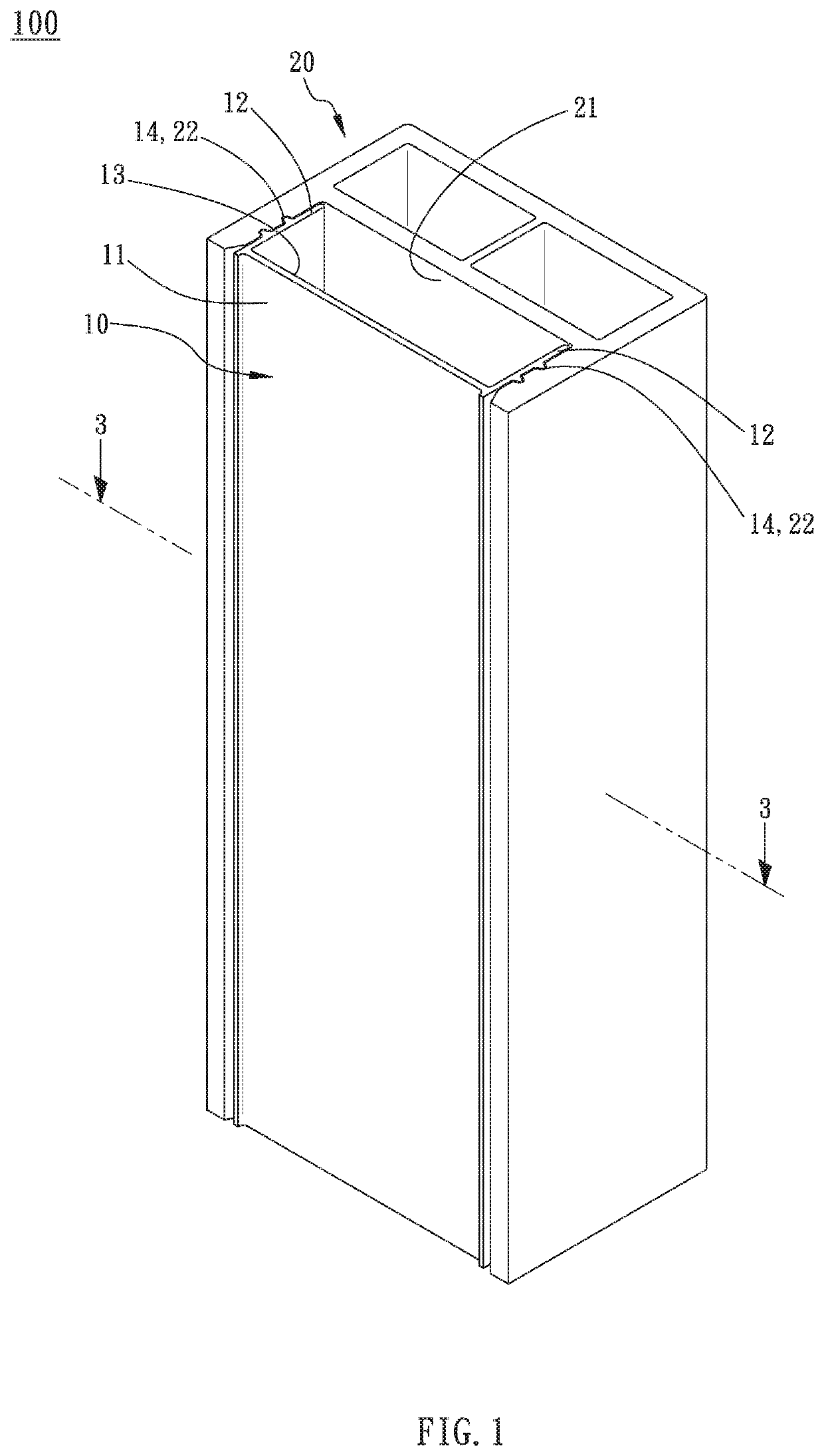
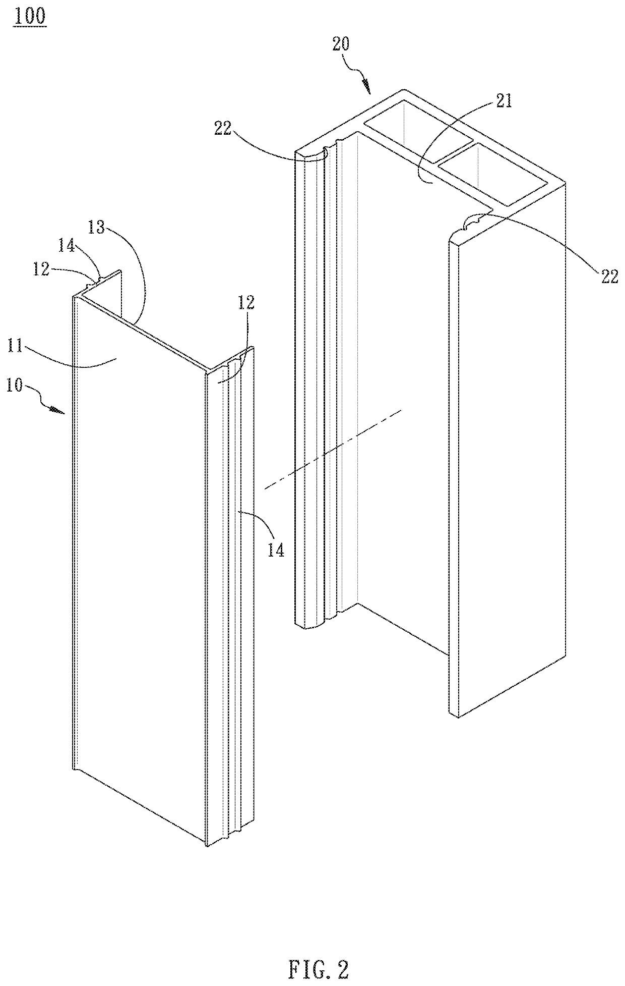
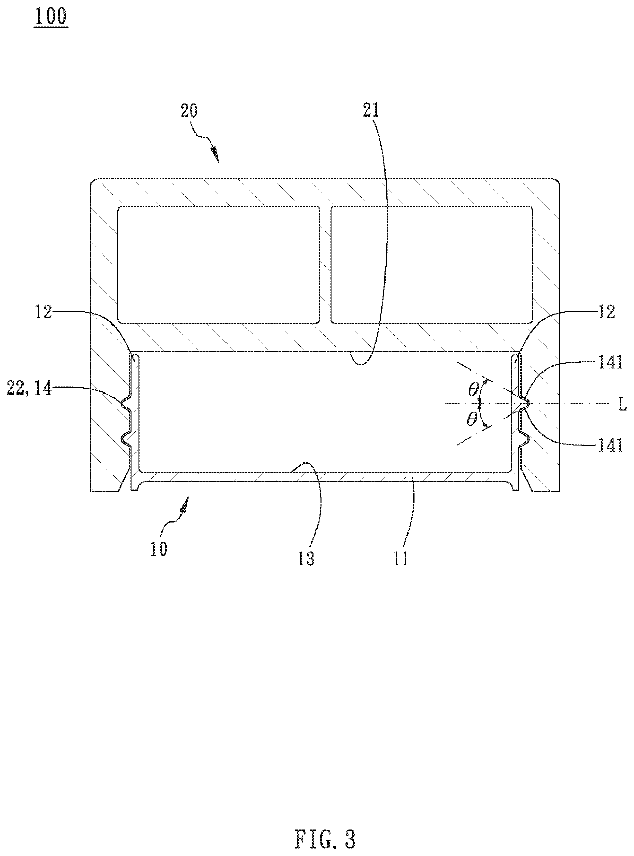
[0025]Referring to FIG. 1 to FIG. 4, in the present invention, a composite material based building material structure 100 comprises a metal member 10 and a combination member 20.

[0026]The metal member 10 is formed in a bar shape. In a preferred embodiment, the metal member 10 is an extrusion of aluminum alloy, with a surface thereof being anodized to form an antioxidant layer thereon, such that the metal member 10 possesses anti-corrosion property. In detail, the metal member 10 comprises a connection plate 11 and two lateral plates 12 disposed on two ends of the connection plate 11. The two lateral plates 12 extend toward an identical side of the connection plate 11, such that a combination groove 13 is formed by the connection plate 11 and the two lateral plates 12. Referring to FIG. 1 and FIG. 3, a sectional profile of the combination groove 13 is formed in a U shape, with one side thereof open and the other side thereof closed. The metal member 10 further comprises a plurality o...

third embodiment

[0036]The two fixation members 50′ are mounted on an outer side of each combination member 20′ and connected between the two neighboring combination members 20′. Referring to FIG. 9 and FIG. 10, each fixation member 50′ comprises a fixation portion 51′ and two positioning portions 52′ disposed on two sides of the fixation portion 51′. Each positioning portion 52′ extends toward one side of the fixation portion 51′. In the third embodiment, each fixation member 50′ is mounted on the combination members 20′ with fixation portion 51′ and positioning portion 52′ resisting against an outer periphery of combination member 20′, such that the two fixation members 50′ are close to and resist against each other, and each fixation portion 51′ is disposed perpendicular to an imaginary line D of each combination member 20′. Afterwards, a plurality of fasteners 53′ are applied on the positioning portion 52′ for fastening the fixation member 50′ with the corresponding combination member 20′, metal...


PUM

PropertyMeasurementUnit
Shapeaaaaaaaaaa

Abstract

A composite material based building material structure includes a metal member and a combination member. The metal member includes a connection plate and two lateral plates disposed on two ends of the connection plate. The two lateral plates extend toward an identical side of the connection plate, forming a combination groove. The metal member includes a plurality of first connection portions on an outer periphery of each lateral plate. The combination member is formed of wood plastic composites, and has a recess for receiving the metal member. The combination member includes a plurality of second connection portions on an inner periphery of the recess, for correspondingly receiving the first connection portions, such that the combination member is mounted on an outer side of the metal member. Thus, the metal member is prevented from moisture, achieving increased life span of the building material structure.

Description

BACKGROUND OF THE INVENTION1. Field of the Invention[0001]The present invention relates to building material structures, and more particularly, to a composite material based building material structure.2. Description of the Related Art[0002]Conventional trellises are mainly formed of a single material, such as wood or metal. The trellises formed of wood or metal have corresponding structural issues. For example, the wood material has solid structure; however, the weight thereof is relatively high, causing laborious issue during transportation. Further, wood material has poor resistance to water and moisture, which easily leads to rottenness and deformation in humid environment, causing deterioration of structural performance of the wood material.[0003]Also, the metal material has greater structural strength; however, when contacting water, oxygen, acids, or other oxidant, the metal material is easily oxidized and corroded, decreasing the life span thereof.SUMMARY OF THE INVENTION[00...

Claims


Application Information

Patent Timeline
IPC IPC(8): E04B1/24E04B1/08E04B1/10E04B1/14
CPCE04B1/24E04B1/08E04B1/10E04B2001/1966E04B2103/04E04B2103/06E04B1/14E04B1/30E04C3/36
Inventor YANG, CHENG-HUNG
Owner YANG CHENG HUNG
Why Eureka
Try Eureka