Image forming apparatus

Active Publication Date: 2017-04-20
CANON KK
View PDF1 Cites 3 Cited by
  • Summary
  • Abstract
  • Description
  • Claims
  • Application Information

AI Technical Summary

Benefits of technology

[0008]Thus, the primary object of the present invention is to provide an image forming apparatus which is capable of minimizing, after the transfer process, its photosensitive member in the amount of the post-transfer latent image, which is pr

Problems solved by technology

Therefore, it is more likely to damage the peripheral surface of a photosensitive drum, being therefore greater in the amount by which the peripheral surface of a photosensitive member is worn than a DC-based method.
However, a DC-based method is likely to suffer from the following problem.
If the photosensitive member is charged while it is suffering from this post-transfer latent image, it is possible that abnormal electrical discharge will occur between the charge roller an

Method used


Image

  • Image forming apparatus
  • Image forming apparatus
  • Image forming apparatus

Examples


embodiment 1

1. Overall Structure and Operation of Image Forming Apparatus

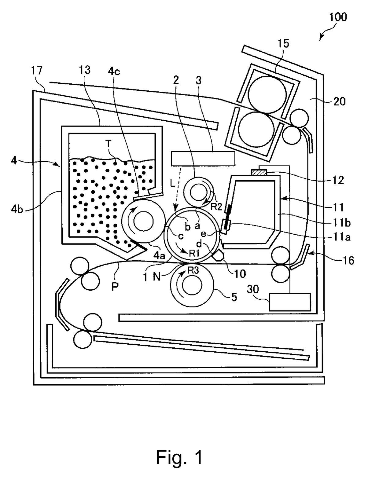
[0017]FIG. 1 is a schematic sectional view of the image forming apparatus 100 in the first embodiment of the present invention. The image forming apparatus 100 in this embodiment is a laser beam printer which uses an electrophotographic method.

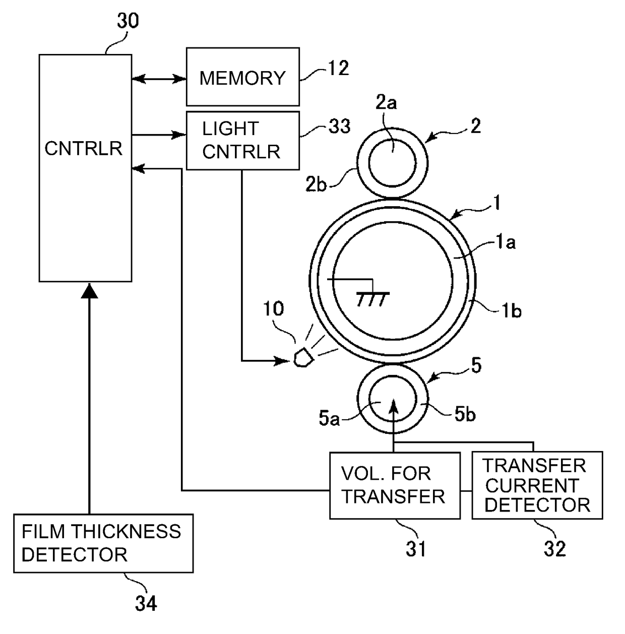
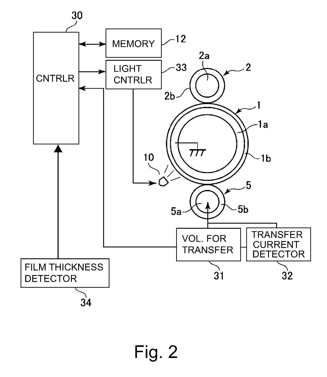
[0018]The image forming apparatus 100 has a photosensitive drum 1 (electrophotographic photosensitive member), as an image bearing member, which is rotatable. The photosensitive drum 1 is made up of an electrically conductive drum 1a (as substrate: FIG. 2) which is formed of aluminum or the like; and a layer 1b (photosensitive layer) formed, as a surface layer, on the peripheral surface of the drum 1a, of an organic or inorganic photoconductive substance. In particular, in this embodiment, the photosensitive drum 1 is provided with an organic photosensitive layer (OPC layer). The drum substrate 1a is electrically grounded. The photosensitive drum 1 is rotationally driven by a driving...


PUM


Abstract

An image forming apparatus includes a rotatable photosensitive drum including a photosensitive layer; a drum charging member contacted or disposed closely to the drum, to be supplied with a DC voltage; a developing device; a transfer member for transferring a toner image onto a toner image receiving member; a device for applying to the transfer member a transfer bias voltage; a light projecting portion for projecting light to the drum before the charging and after the image transfer; a controller for controlling a quantity of the projected light, on the basis of the transfer bias and a film thickness of the photosensitive layer, wherein under a condition that the transfer bias is the same, the light amount controlled by the controller is smaller when the film thickness is a second value than when it is a first value, the second value being smaller than the first value.

Description

FIELD OF THE INVENTION AND RELATED ART[0001]The present invention relates to an image forming apparatus which uses an electrophotographic method.[0002]Conventionally, in an image forming apparatus which uses an electrophotographic method, the peripheral surface of its photosensitive member (electrophotographic photosensitive member) is uniformly charged by its charging means. Then, the charged peripheral surface of the photosensitive member is exposed in accordance with the image data by an exposing means. Consequently, an electrostatic latent image is formed on the peripheral surface of the photosensitive drum. To the electrostatic latent image, toner is adhered. As a result, a toner image is formed on the peripheral surface of the photosensitive drum. Then, the toner image is transferred onto recording medium such as a sheet of paper. As the photosensitive member, a rotatable photosensitive drum, that is, a photosensitive member in the form of a drum, is widely in use.[0003]In rec...

Claims


Application Information

Patent Timeline
IPC IPC(8): G03G15/16G03G21/00
CPCG03G15/1665G03G15/043G03G21/08
Inventor KISHI, YOSUKETODA, ATSUSHIFUKUSHIMA, NAOKI
Owner CANON KK
Why Eureka
Try Eureka