Orthodontic clip device

Inactive Publication Date: 2016-04-21
KIM KI SOO
View PDF5 Cites 12 Cited by
  • Summary
  • Abstract
  • Description
  • Claims
  • Application Information

AI Technical Summary

Benefits of technology

The orthodontic clip device described in this patent is easy to use and helps maintain the stability and clean appearance of the teeth being treated. The device consists of a metallic clip and wire that are inserted into the mouth and held together by an elastic clip. This design allows for easier and faster orthodontic treatment, reducing the time and cost associated with this process.

Problems solved by technology

In particular, a case where the teeth are not equally grown is called malocclusion, in the case of the malocclusion, it externally looks bad, it is not possible to functionally chew the food, and the pronunciation can be adversely affected.
Furthermore, when leaving the malocclusion, the possibility of the occurrence of dental caries or periodontal disease becomes increase, and other parts of the body are also affected for a long period of time, which may induce or further worsen other diseases.
However, since all the existing methods are methods of fixing the clip base bonded to the teeth by inserting the connecting wire from the front based on the teeth, the insertion and fixing works of the connecting wire are structurally very hard and inconvenience, and the problems of structural inconvenience and hygienic defect, such as a decline in orthodontic force to the teeth and the easy detachment of the connecting wire from the clip base itself are not still solved.

Method used


Image

  • Orthodontic clip device
  • Orthodontic clip device
  • Orthodontic clip device

Examples


Embodiment Construction

[0024]Exemplary embodiments of the present invention will be described below in more detail with reference to the accompanying drawings. The present invention may, however, be embodied in different forms and should not be construed as limited to the embodiments set forth herein. Rather, these embodiments are provided so that this disclosure will be thorough and complete, and will fully convey the scope of the present invention to those skilled in the art. Throughout the disclosure, like reference numerals refer to like parts throughout the various FIGS. and embodiments of the present invention.

[0025]Hereinafter, a specific configuration relation and its embodying principle of the orthodontic clip device according to the present invention will be described in detail with reference to the drawings of the preferred embodiments.

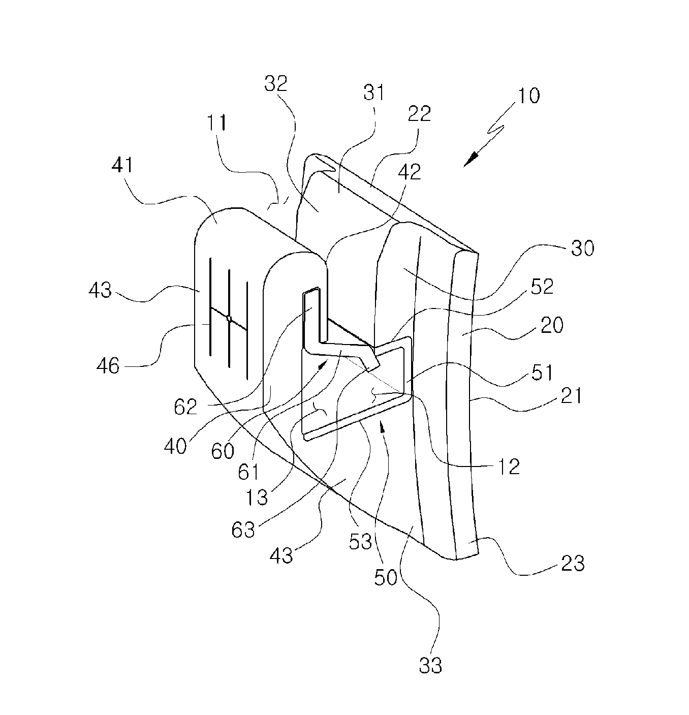
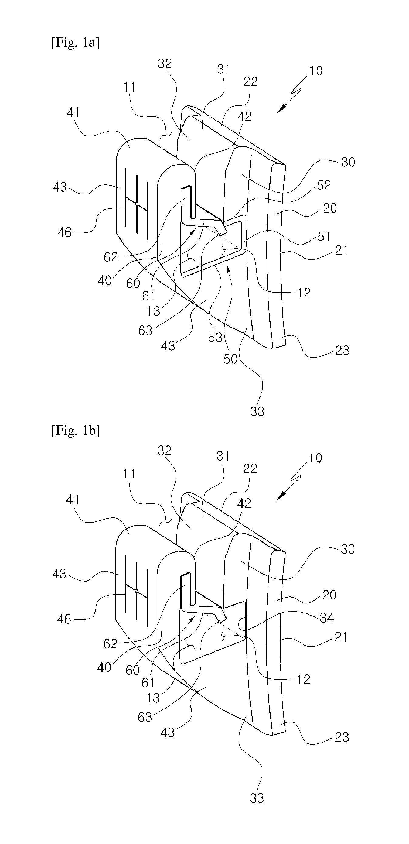
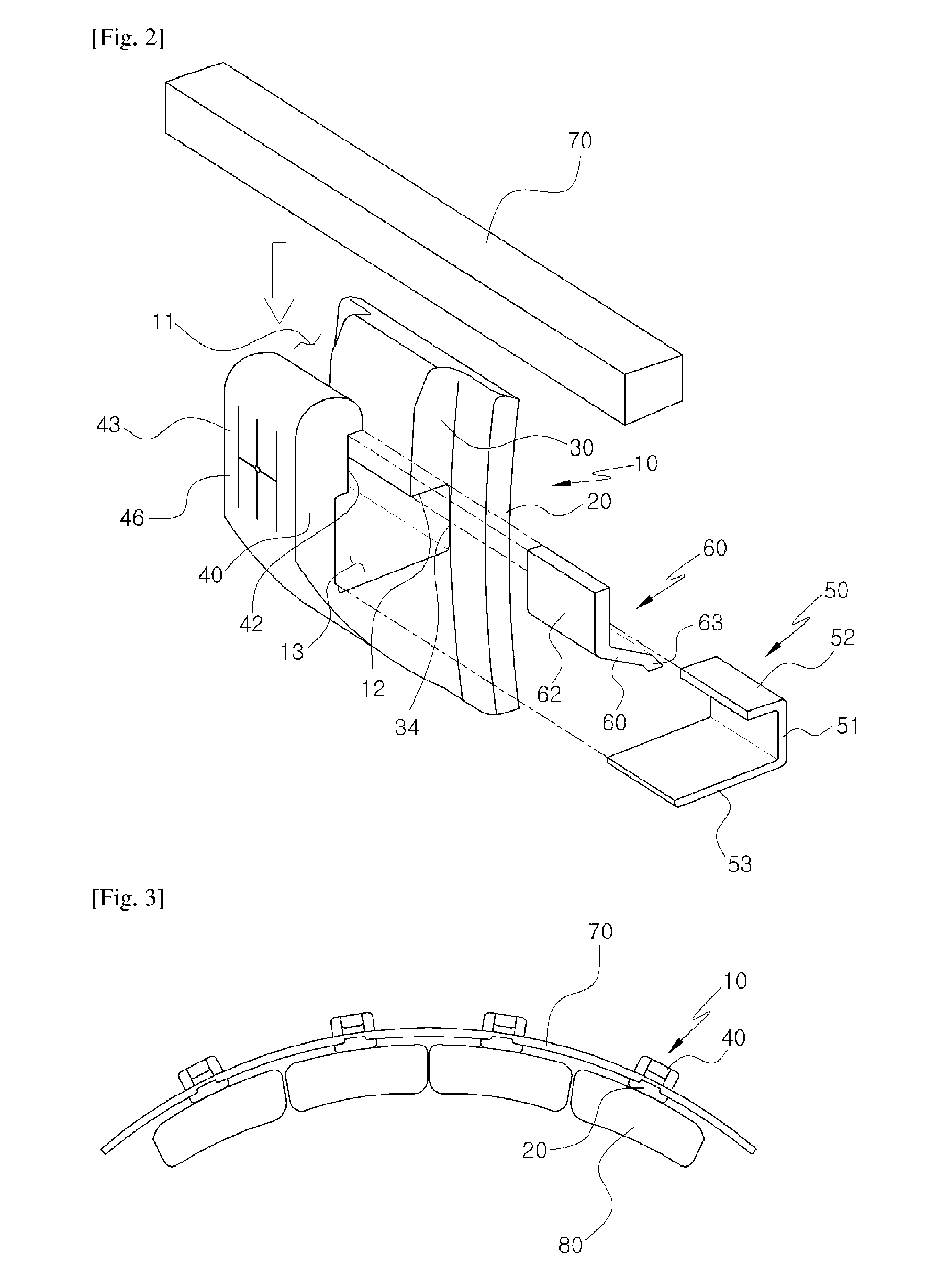
[0026]Basically, as illustrated in the use state diagrams of FIGS. 3 and 4, in the present invention, a clip base 10 as an orthodontic clip usually made of a cer...


PUM


Abstract

The present invention relates to a clip device for orthodontic treatment wherein appropriate force is applied to a tooth so as to move the tooth to a desired position, thereby correcting the tooth into a normal tooth alignment, and the clip device comprises: a clip base made of a ceramic material, having a base portion directly joined to a tooth, projecting an inner back portion toward the outside of the base portion, having a wire insertion hole with an opened upper portion formed between the inner back portion and an outer front portion, which is projected at a distance from the inner back portion, for allowing a connection wire to be inserted therein, and having a wire fixing hole and a clip operation hole formed below the wire insertion hole; and an elastic clip having a fixing clip, which is a fixing means made from a metal material, integratedly coupled to the wire fixing hole toward the inner back portion and the clip operation hole toward the outer front portion of which the spaces communicate with each other at the lower portion of the wire insertion hole, and formed from a resilient means made of a metal material at the upper portion of the clip operation hole, in order to resiliently support, bind and fix the connection wire inserted through the wire insertion hole of the clip ase to the wire fixing hole and to induce sliding in a binding operation of the connection wire.

Description

TECHNICAL FIELD[0001]The present invention relates to an orthodontic clip device used for the correction process to a normal teeth correction state by applying appropriate forces to the teeth to move the teeth to the desired location, and more particularly, to an orthodontic clip device in which an orthodontic clip and a connecting wire for connecting and grasping the orthodontic clip can be naturally elastically bound through elastic restoration of a elastic member configured in the orthodontic clip, while being simply inserted to the bottom from the top of the orthodontic clip, thereby enabling the stable fixation and clean and beautiful wearing state of the teeth, while providing the easy and simple treatment.BACKGROUND ART[0002]In general, the orthodontic (dentition correction correction) treatment means a treatment of correcting a variety of skeletal disharmony that may occur in the course of growth, including simply aligning the crooked teeth to allow a normal teeth function, ...

Claims


Application Information

Patent Timeline
IPC IPC(8): A61C7/28A61C7/16A61C7/14
CPCA61C7/28A61C7/16A61C7/148A61C7/14A61C7/30
Inventor KIM, KI SOO
Owner KIM KI SOO
Why Eureka
Try Eureka