High-Resolution Stripmap SAR Imaging

a stripmap and high-resolution technology, applied in the field of remote sensing, can solve the problems of very high transmission power, limited azimuth length of swaths of spotlight mode, and the above-stated methodologies used for improving azimuth resolution suffer from some drawbacks, so as to achieve the effect of increasing integration times

Active Publication Date: 2016-04-21
THALES ALENIA SPACE ITAL SPA
View PDF0 Cites 21 Cited by
  • Summary
  • Abstract
  • Description
  • Claims
  • Application Information

AI Technical Summary

Benefits of technology

[0034]The object of the present invention is that of providing a stripmap SAR imaging method that enables achieving better azimuth resolutions with respect to those obtainable with current SAR acquisition techniques of the stripmap type, and which does not suffer from the previously described drawbacks. The above-stated object is achieved by the present invention insofar as it relates to a SAR imaging method and a SAR system, as defined in the appended claims.
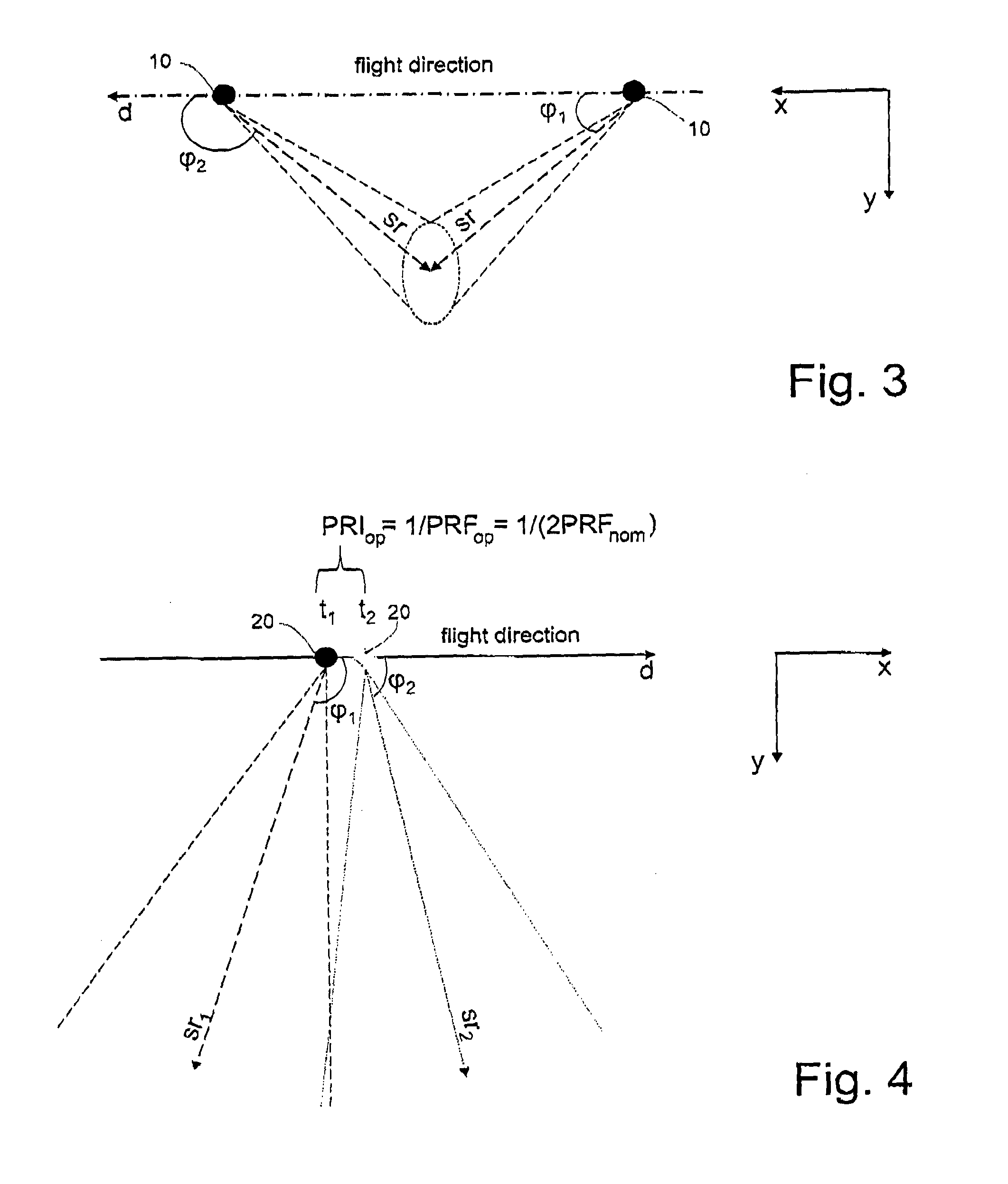
[0041]In particular, the radar beams transmitted and received in two radar transmission and reception operations performed in two immediately successive time instants and related to two different SAR acquisitions in stripmap mode are contiguous along the azimuth, thereby increasing the integration times with respect to those obtainable via any single one of the N SAR acquisitions in stripmap mode performed.

Problems solved by technology

Both of the above-stated methodologies used for improving the azimuth resolution suffer from some drawbacks.
In particular, the use of very wide antenna beams requires using very high transmission powers, while the spotlight mode introduces limitations on the azimuth length of the swaths.
The biggest contraindication of this technique is the complexity; in fact, this technique requires the simultaneous use of M receivers and M “small” antennas (or a large one partitioned into M sub-blocks) and therefore requires high transmission power to achieve adequate product sensitivity.
Also in this case, the biggest contraindication of the angular division techniques is the complexity; in fact, these techniques contemplate the simultaneous use of M receivers and M “small” antennas (or a large one partitioned into M sub-blocks) and therefore require high transmission power to achieve adequate product sensitivity.

Method used


Image

  • High-Resolution Stripmap SAR Imaging
  • High-Resolution Stripmap SAR Imaging
  • High-Resolution Stripmap SAR Imaging

Examples


Embodiment Construction

[0051]The following description is provided to enable an expert in the field to embody and use the invention. Various modifications to the embodiments shown will be immediately obvious to experts and the generic principles described herein could be applied to other embodiments and applications without departing from the scope of protection of the present invention.

[0052]Thus, the present invention is not intended to be limited to just the embodiments described and shown herein, but is to be accorded the widest scope consistent with the principles and features disclosed herein and defined in the appended claims.

[0053]The present invention derives from the applicant's insight to exploit the steering capability of the antennas used in the SAR sensors in a non-conventional manner. The applicant then conceived a multi-beam and multi-temporal SAR acquisition technique that exploits the transmission and reception characteristics of a SAR sensor in time-sharing.

[0054]In particular, the idea...


PUM


Abstract

A SAR imaging method performs N SAR acquisitions in stripmap mode of the earth's surface using a synthetic aperture radar transported by an aerial or satellite platform and including a single, non-partitioned antenna and a single receiver coupled thereto. All N SAR acquisitions are performed using the same predetermined elevation angle relative to the nadir of the synthetic aperture radar and using a respective squint angle relative to the flight direction of the synthetic aperture radar. Radar transmission and reception operations are time interleaved with other N-1 SAR acquisitions, resulting in the respective acquisition directions being parallel to each other and not parallel to acquisition directions of other N-1 SAR acquisitions. Radar beams in two immediately successive time instants and related to two different SAR acquisitions are contiguous along the azimuth. SAR images may be generated using all the N SAR acquisitions having an enhanced azimuth resolution.

Description

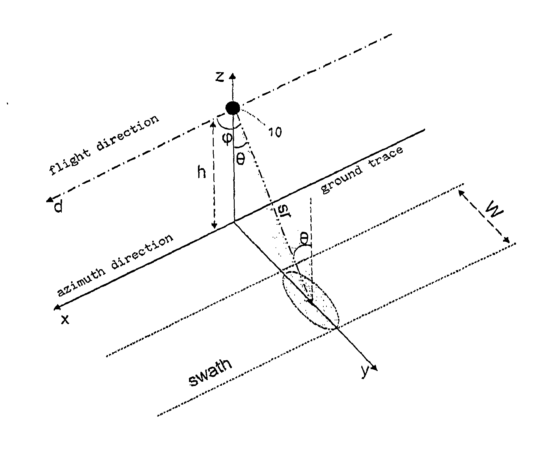
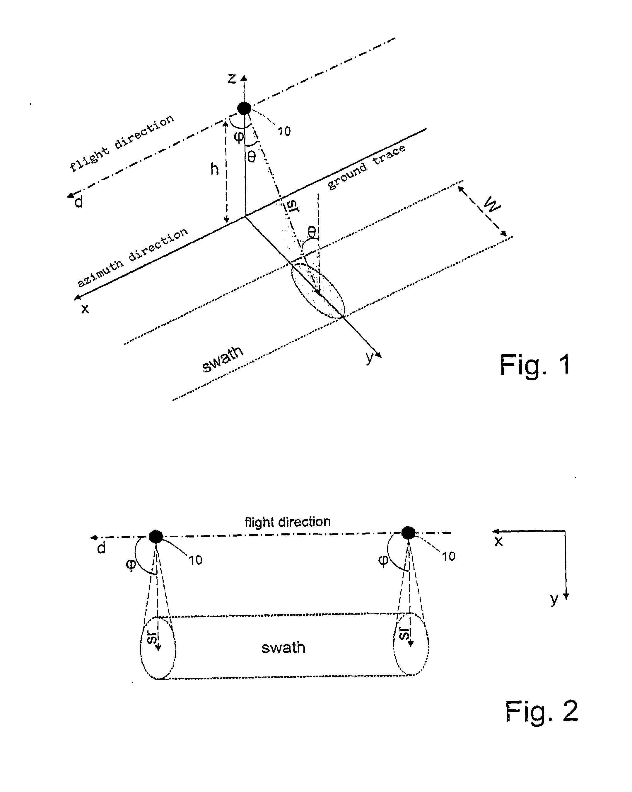
TECHNICAL FIELD OF INVENTION[0001]The present invention relates to remote sensing by means of Synthetic Aperture Radar (SAR) in general and, in particular, to an innovative method for high-resolution stripmap SAR imaging.STATE OF THE ART[0002]A typical reference geometry for generating SAR images of the earth's surface is shown in FIG. 1. With regard to this, it is wished to underline the fact that in FIG. 1 (and also in the following figures that will be presented and described hereinafter), the earth's surface is (and will be) shown “flat” only for convenience and simplicity of illustration and description, without any loss of generality.[0003]In particular, FIG. 1 schematically shows a synthetic aperture radar (hereinafter called a SAR sensor, for simplicity of description) 10 that moves along a flight direction d at an altitude h (with respect to the earth's surface) assumed to be substantially constant. As is known, the altitude h of the SAR sensor 10 is measured along a nadir ...

Claims


Application Information

Patent Timeline
Patent Type & Authority Applications(United States)
IPC IPC(8): G01S13/90
CPCG01S2013/9041G01S13/9035G01S13/904G01S13/9041G01S13/90G01S13/9054G06T1/0007G06T7/60G06T2207/10044G06T2207/30181
Inventor CALABRESE, DIEGO
Owner THALES ALENIA SPACE ITAL SPA
Why Eureka
Try Eureka