Package structure with optical barrier, optical package structure and manufacturing methods thereof

Active Publication Date: 2016-04-21
SENSORTEK TECH
View PDF8 Cites 15 Cited by
  • Summary
  • Abstract
  • Description
  • Claims
  • Application Information

AI Technical Summary

Benefits of technology

[0027]These and other objectives of the present invention will no doubt become obvious to those of ordinary skill in the art afte

Problems solved by technology

However, the method not only increases the process time, but since the spacers need additional space for accommodating them, the minimum package structure is hard to achieve.
With the trend for reducing elements' volume, all of method for forming the metal frame, plastic ca

Method used


Image

  • Package structure with optical barrier, optical package structure and manufacturing methods thereof
  • Package structure with optical barrier, optical package structure and manufacturing methods thereof
  • Package structure with optical barrier, optical package structure and manufacturing methods thereof

Examples


Embodiment Construction

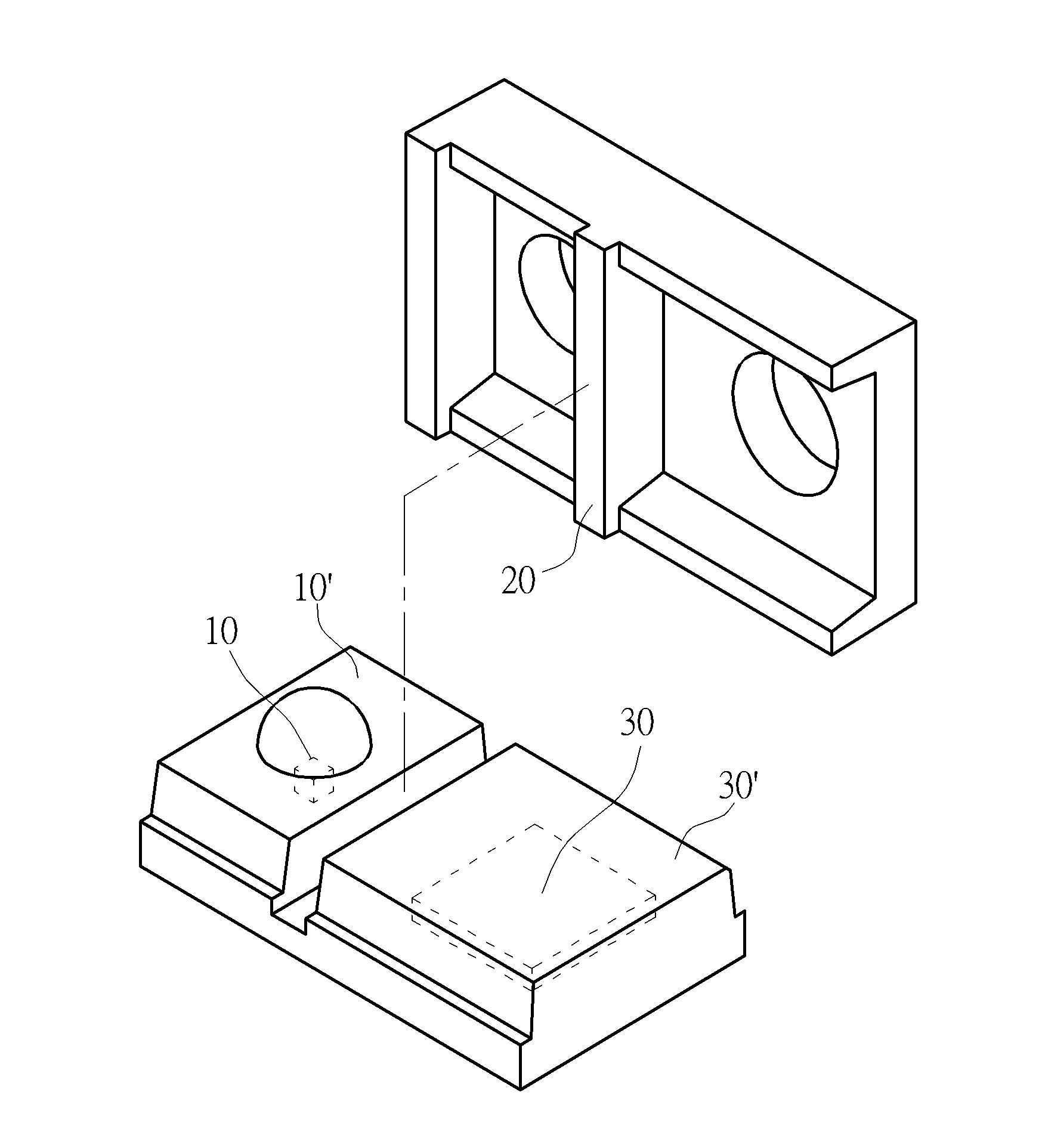
[0039]The present invention provides a package structure with an optical barrier, a method for forming optical package structure, and the formed optical package structure. In the present invention, the package material covers the emitter, the detector and the optical barrier, so the optical barrier is sealed within the package material. Preferably, there is still a distance between the optical barrier and the surface of the package material.

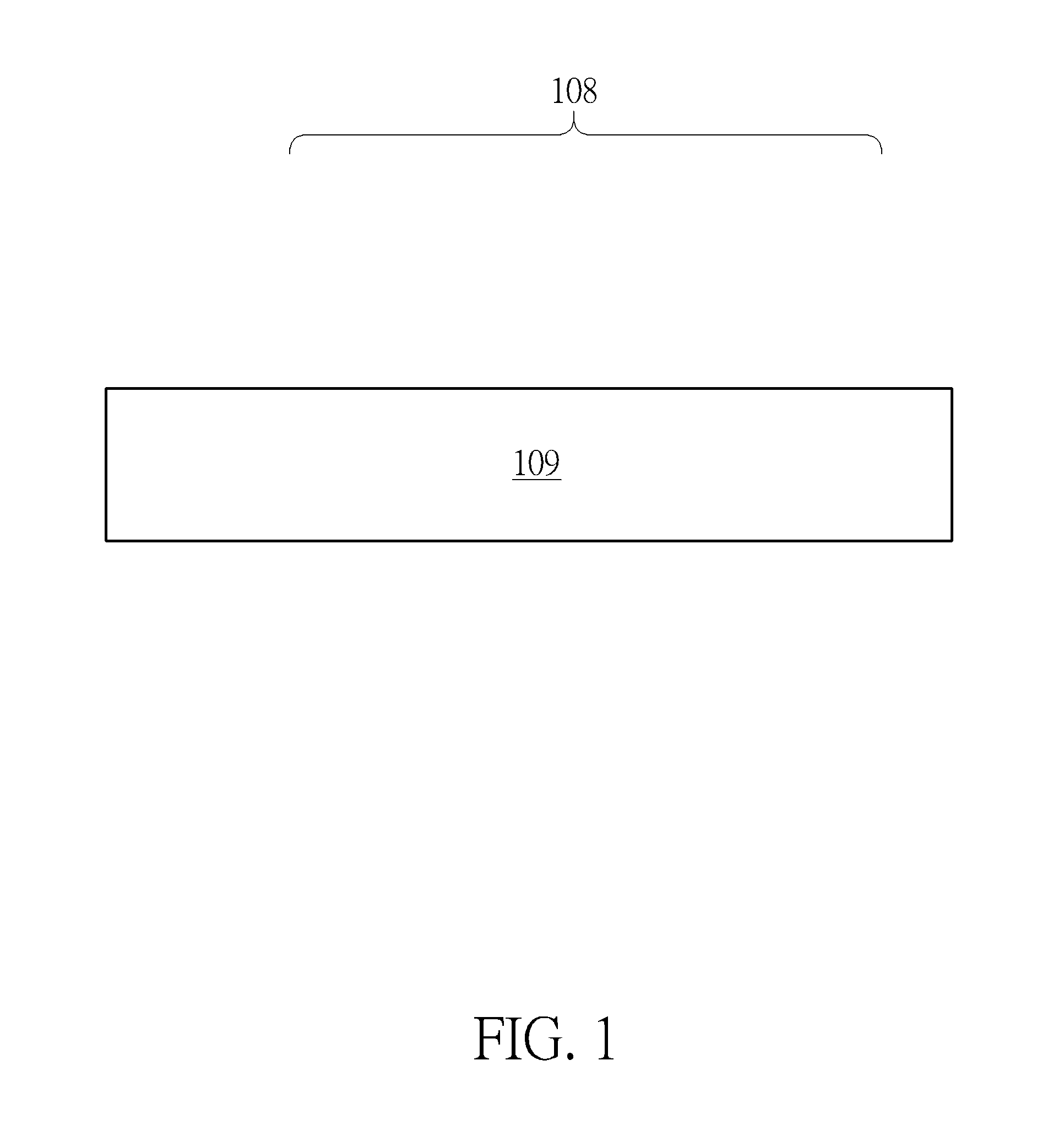
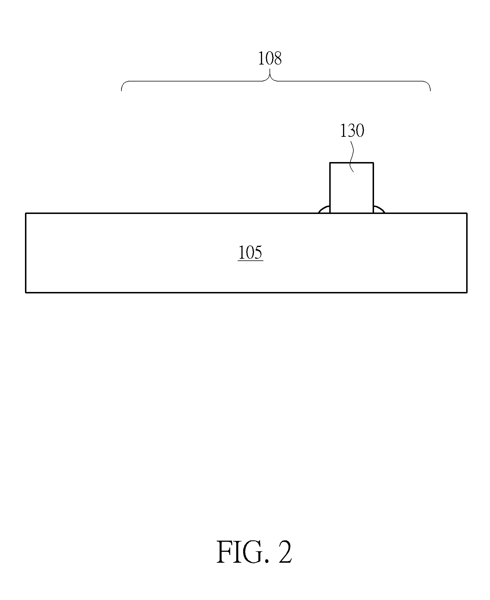
[0040]The present invention provides a method for forming optical package structure. FIGS. 1-6 show a method for forming an optical package structure of the present invention. First of all, please refer to FIG. 5, in which a substrate 109 is provided. The substrate 109 includes an emitter 110, a detector 120 and an optical barrier 130 disposed thereon. The optical barrier 130 disposed between the emitter 110 and the detector 120, is used for selectively shielding the excess optical signal 111 of the emitter 110, so as to prevent the signal crosst...


PUM


Abstract

A package structure with an optical barrier is provided. An emitter for emitting an optical signal and a detector for receiving the optical signal are disposed on a substrate. The optical barrier is disposed between the emitter and the detector for shielding the excess optical signal. A package material is used to completely cover the optical barrier, the emitter and the detector so that the optical barrier is completely disposed within the package material.

Description

CROSS REFERENCE TO RELATED APPLICATIONS[0001]This application claims priority to U.S. Application No. 62 / 063,963, filed on Oct. 15, 2014.BACKGROUND OF THE INVENTION[0002]1. Field of the Invention[0003]The present invention relates to a method for forming an optical package structure, and the formed optical package structure. In particular, to a package structure having an optical barrier and the manufacturing method thereof. In the optical package structure, the optical barrier is completely disposed within the package material, having the advantages such as being compatible with traditional production methods.[0004]2. Description of the Prior Art[0005]With the development of portable electronic products, the application of touch screens becomes increasingly common. A touch screen is a touch-enabled display panel, such as a touch sensitive transparent panel surface. A touch screen allows the user using finger or stylus to touch the screen, and to select or to move the cursor. In ord...

Claims


Application Information

Patent Timeline
IPC IPC(8): H01L31/0232H01L31/12H01L31/18H01L31/0203G01S17/04
CPCH01L31/02325H01L31/18H01L31/12H01L31/0203H01L31/02327G01S7/4813H01L2224/48091H01L2224/48465H01L2224/73265H01L31/173G01S17/04H01L2924/00014
Inventor HSU, FENG-JUNGYANG, CHU-YUANHSU, YUAN-CHINGCHANG, YI-HUA
Owner SENSORTEK TECH
Why Eureka
Try Eureka