Gate Leakage Based Low Power Circuits

a leakage-based, low-power technology, applied in the direction of generating/distributing signals, pulse techniques, instruments, etc., can solve the problem that continuous monitoring during low-power mcu operation may consume and achieve the effect of consuming non-trivial amounts of power and minimizing power

Inactive Publication Date: 2016-04-21
AMBIQ MICRO
View PDF8 Cites 22 Cited by
  • Summary
  • Abstract
  • Description
  • Claims
  • Application Information

AI Technical Summary

Problems solved by technology

Furthermore, it is of no relevance in such systems which specific voltage levels are selected to represent each of the logic states.
However, as is also known, continuous monitoring during low-power MCU operation may consume non-trivial amounts of power, due in part to large power dissipated by voltage dividers that are part of the voltage monitoring circuits.

Method used


Image

  • Gate Leakage Based Low Power Circuits
  • Gate Leakage Based Low Power Circuits
  • Gate Leakage Based Low Power Circuits

Examples


Embodiment Construction

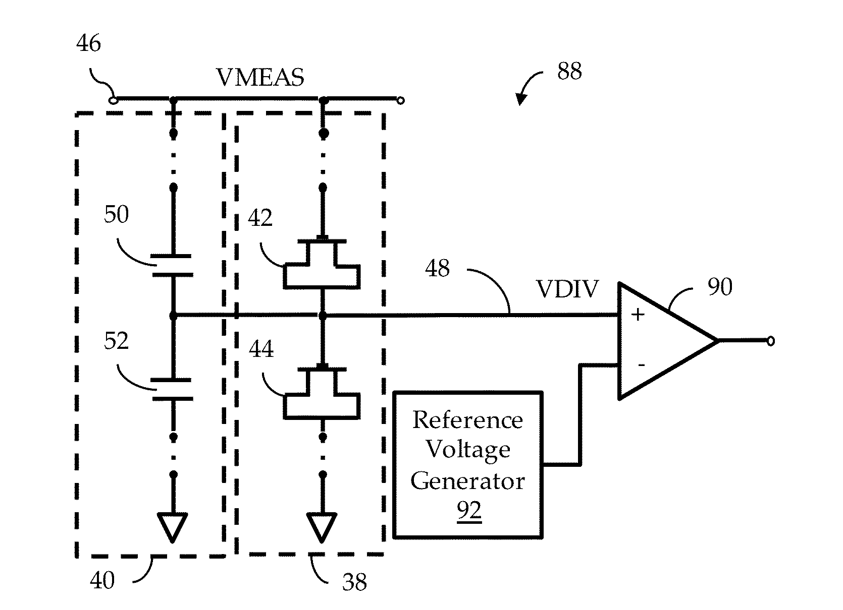
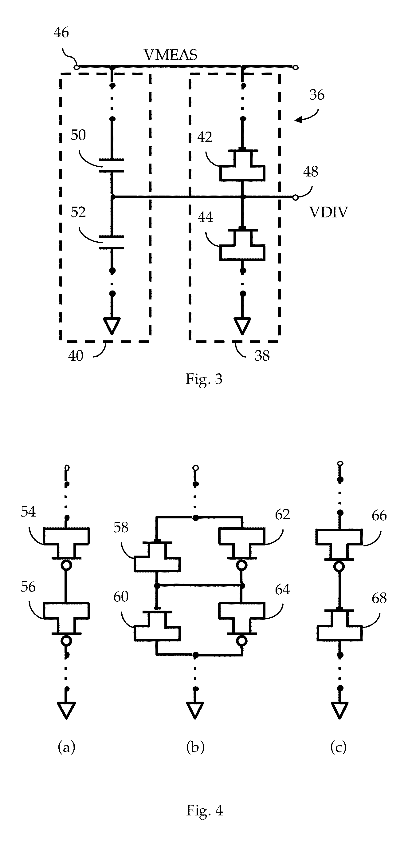
[0044]FIG. 3 illustrates, in schematic form, a voltage divider facility 36 adapted to operate in accordance to some embodiments. According to one embodiment, the voltage divider facility 36 includes a GL-based voltage divider facility 38 and a capacitive facility 40.

[0045]In the illustrated embodiment, the GL-based voltage divider facility 38 includes a stack of transistors that includes, in this simple example, a first transistor 42 and a second transistor 44. The first transistor 42 has its gate terminal coupled to a measured voltage 46, here labeled as “VMEAS”, and has both source and drain terminals shorted together. Alternatively, in a taller stack, the gate terminal of the first transistor 42 may be coupled to the measured voltage 46 via one or more additional transistors (see, e.g., FIG. 14). The shorted source and drain terminals of the first transistor 42 are coupled to the gate terminal of the second transistor 44. The gate terminal of the second transistor 44 is also coup...


PUM


Abstract

A low power voltage divider facility using gate leakage characteristics to divide voltage levels of sub-threshold and near-threshold circuits. The divider comprises a gate leakage based divider facility, and, optionally, a capacitive divider facility.

Description

CROSS REFERENCE TO RELATED APPLICATIONS[0001]This application is related to the following:[0002]1. Provisional Application Ser. No. 62 / 066,218, filed 20 Oct. 2014 (“Parent Provisional”);[0003]2. PCT Application No. PCT / US15 / 50239 filed 15 Sep. 2015 (“Related Application 1”);[0004]3. U.S. application Ser. No. 14 / 855,105, filed 15 Sep. 2015 (“Related Application 2”);[0005]4. U.S. application Ser. No. [Docket No. JAM012], filed simultaneously herewith (“Related Application 3”);[0006]5. U.S. application Ser. No. [Docket No. JAM014], file simultaneously herewith (“Related Application 4”); and[0007]6. U.S. application Ser. No. [Docket No. JAM015], filed simultaneously herewith (“Related Application 5”).[0008]This application claims priority to the Parent Provisional, and hereby claims benefit of the filing date thereof pursuant to 37 CFR §1.78(a)(4).[0009]The subject matter of the Parent Provisional and the Related Applications, each in its entirety, is expressly incorporated herein by re...

Claims


Application Information

Patent Timeline
Patent Type & Authority Applications(United States)
IPC IPC(8): H03K17/687H03M1/12G01R19/00G05F1/56
CPCH03K17/687G01R19/0084H03M1/12G05F1/56G06F1/3237G06F1/3287G06F1/06G06F13/102G05F1/575Y02D10/00H03L7/18H03L7/06H03L7/181Y02B70/10H02M1/0045G06F1/12G06F11/3041G06F11/3414H03L7/00G06F1/3296H02M3/158
Inventor HANSON, SCOTTBARTLETT, DONALD MARKLU, YANNING
Owner AMBIQ MICRO
Why Eureka
Try Eureka