
Low Power Automatic Calibration Method for High Frequency Oscillators

a high frequency oscillator, low-power technology, applied in the direction of pulse technique, generating/distributing signals, instruments, etc., can solve the problems of constant consumption of non-trivial amount of power, tendency to leave plls enabled continuously, and non-trivial output. achieve the effect of avoiding unnecessary proliferation of numbers

Active Publication Date: 2016-04-21
AMBIQ MICRO
View PDF0 Cites 4 Cited by
  • Summary
  • Abstract
  • Description
  • Claims
  • Application Information

AI Technical Summary

Benefits of technology

The patent text describes a clock calibration method that can adjust the frequency of a measured clock to match a reference clock. The method involves selectively enabling a reference clock oscillator to develop reference clock pulses at a selected reference frequency and a measured clock oscillator to develop measured clock pulses at a frequency determined as a function of an adjustment value. The method can adjust the adjustment value as a function of a difference between the count of the measured clock pulses and a selected target value or the frequency of the measured clock relative to the reference clock. The technical effect of this invention is to provide a more accurate and efficient way to calibrate clocks in electronic systems.

Problems solved by technology

Furthermore, it is of no relevance in such systems which specific voltage levels are selected to represent each of the logic states.
However, as is also known, a PLL continuously consumes a non-trivial amount of power while in operation.
While it is possible to selectively enable the PLL only when needed, the output tends to be relatively unstable for a period of time after the PLL is enabled.
As a result, there is a tendency to leave PLLs enabled continuously, with concomitant power dissipation.

Method used


Image

  • Low Power Automatic Calibration Method for High Frequency Oscillators
  • Low Power Automatic Calibration Method for High Frequency Oscillators
  • Low Power Automatic Calibration Method for High Frequency Oscillators

Examples


Embodiment Construction

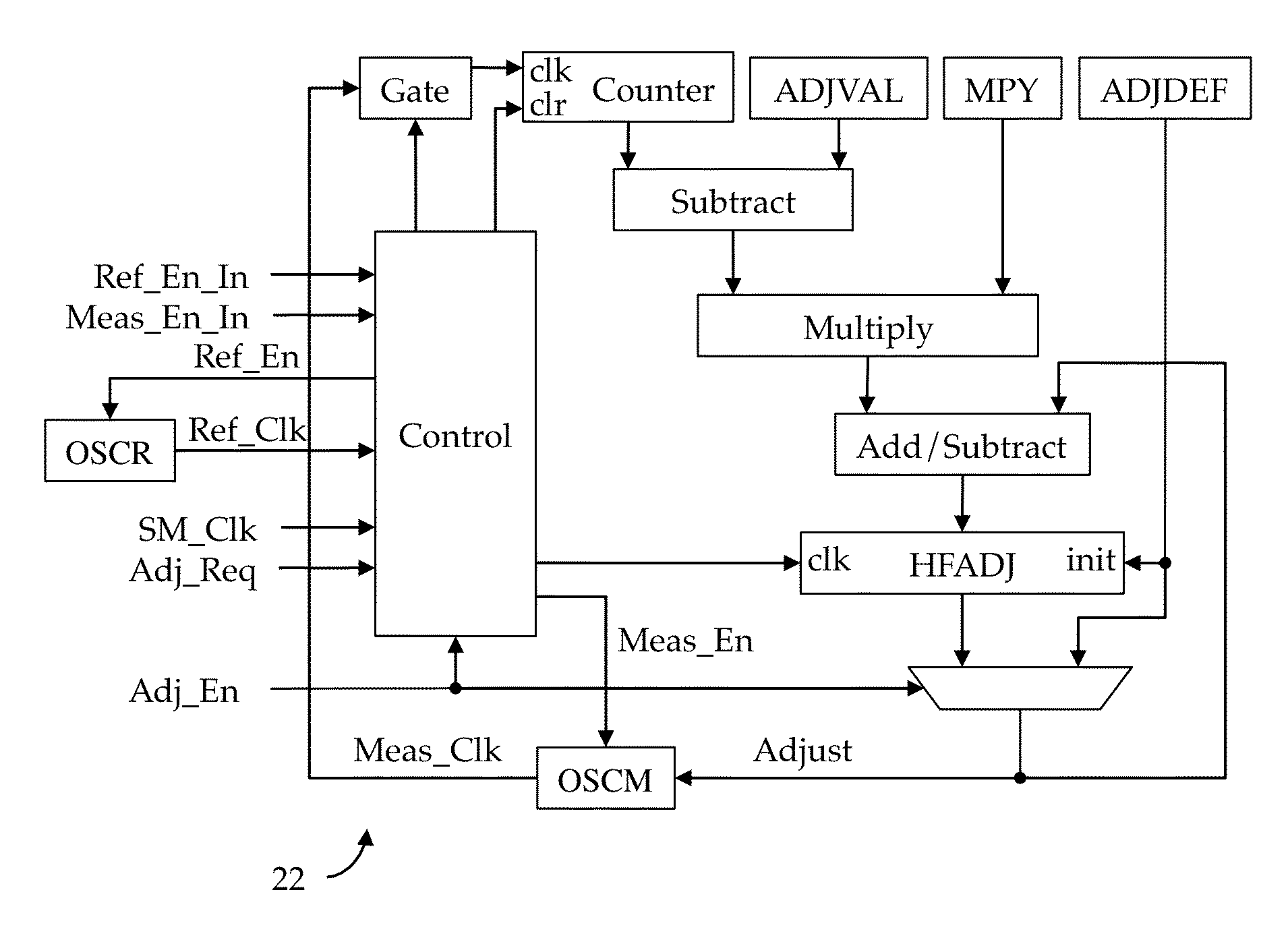
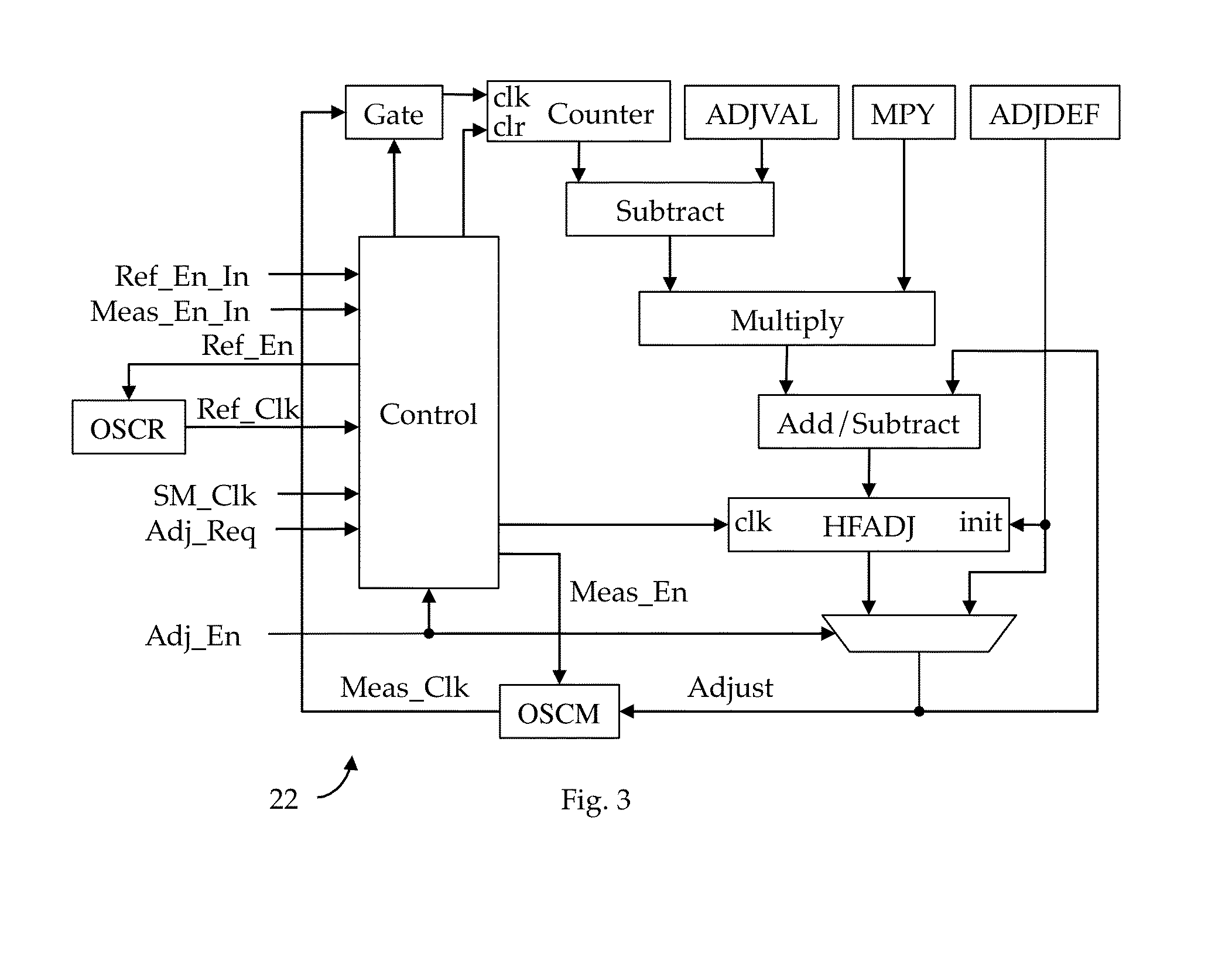
[0027]Shown in FIG. 3 is one embodiment of a clock calibrator 22 adapted to effectively and efficiently solve all of the above issues discussed above with respect to the known prior art clock calibrators. In accordance with this embodiment, a clock to be adjusted, Meas_Clk, is developed by a resistor-capacitor (“RC”) oscillator OSCM, whose frequency is controlled by an Adjust value in a monotonic fashion. A reference clock, Ref_Clk, is developed by a high accuracy crystal oscillator, OSCR, adapted to oscillate at a crystal-specific frequency which may be at a lower frequency than OSCM. In general, the frequency adjustment process is controlled by a Control clocked by a control clock SM_Clk, selected to be either Ref_Clk, Meas_Clk or be developed by a third oscillator (not shown). In the illustrated embodiment, Control is instantiated as a finite state machine.

[0028]In accordance with one embodiment, illustrated generally in FIG. 4, the frequency adjustment process comprises the foll...


PUM


Abstract

A clock calibrator for use in an electronic system comprising an integrated circuit such as a microcontroller. The clock calibrator embodies a frequency adjustment facility adapted dynamically to adjust the frequency of one or more high-frequency clock generators as a function of a lower-frequency reference clock.

Description

CROSS REFERENCE TO RELATED APPLICATIONS[0001]This application is related to the following:[0002]1. Provisional Application Ser. No. 62 / 066,218, filed 20 Oct. 2014 (“Parent Provisional”);[0003]2. PCT Application No. PCT / US15 / 50239 filed 15 Sep. 2015 (“Related Application 1”); and[0004]3. U.S. application Ser. No. 14 / 855,105, filed 15 Sep. 2015 (“Related Application 2”).[0005]This application claims priority to the Parent Provisional, and hereby claims benefit of the filing date thereof pursuant to 37 CFR §1.78(a)(4).[0006]The subject matter of the Parent Provisional and the Related Applications, each in its entirety, is expressly incorporated herein by reference.BACKGROUND OF THE INVENTION[0007]1. Field of the Invention[0008]The present invention relates to a method and apparatus for calibrating a high frequency oscillator.[0009]2. Description of the Related Art[0010]In general, in the descriptions that follow, the first occurrence of each special term of art that should be familiar ...

Claims


Application Information

Patent Timeline
Patent Type & Authority Applications(United States)
IPC IPC(8): H03L7/00
CPCH03L7/00G06F1/3237G06F1/3287G06F1/06G06F13/102G05F1/56H03K17/687G05F1/575Y02D10/00H03L7/18H03L7/06H03L7/181Y02B70/10H02M1/0045G06F1/12G06F11/3041G06F11/3414G01R19/0084H03M1/12G06F1/3296H02M3/158
Inventor SHEAFOR, STEPHEN JAMES
Owner AMBIQ MICRO
Learn More