Wearable camera

a technology of wearing a camera and a camera body, which is applied in the field of wearable cameras, can solve the problems of not being taken into consideration, difficult to verify the discharge of guns and the like executed by police officers, and become a problem, so as to achieve the effect of improving the operability of the video recording button and being convenient to opera

Inactive Publication Date: 2016-04-21
PANASONIC INTELLECTUAL PROPERTY MANAGEMENT CO LTD
View PDF6 Cites 28 Cited by
  • Summary
  • Abstract
  • Description
  • Claims
  • Application Information

AI Technical Summary

Benefits of technology

[0007]An objective of the present disclosure is to provide a wearable camera which is set in an operation mode so as to be able to instantly perform imaging at the scene.
[0012]According to the wearable camera of the present disclosure, the video recording button is disposed on one side having the center line as a boundary on the frontal face of the body of the wearable camera, and the mode changeover switch is disposed on the side thereof. Therefore, for example, the video recording button and the mode changeover switch can be easily operated with the index finger while putting a hand on the chest. As a mode having the highest frequency of use in case of emergency is positioned at the one end of the slot, the video recording button and the mode changeover switch can be appropriately used at the same time even in case of emergency. Since button is provided in the area on one side having the center line as a boundary, operability of the video recording button is improved.

Problems solved by technology

In recent years, particularly in the United States, difficulties in verification regarding discharging of gun and the like executed by a police officer, have become a problem.
However, the configuration of the wearable camera disclosed in Japanese Patent Unexamined Publication No. 2004-356970 has a disadvantage in that the aforementioned circumstances are not taken into consideration.

Method used


Image

  • Wearable camera
  • Wearable camera
  • Wearable camera

Examples


Embodiment Construction

[0028]Hereinafter, favorable exemplary embodiments of a wearable camera according to the present disclosure will be described in detail with reference to FIGS. 1 to 6.

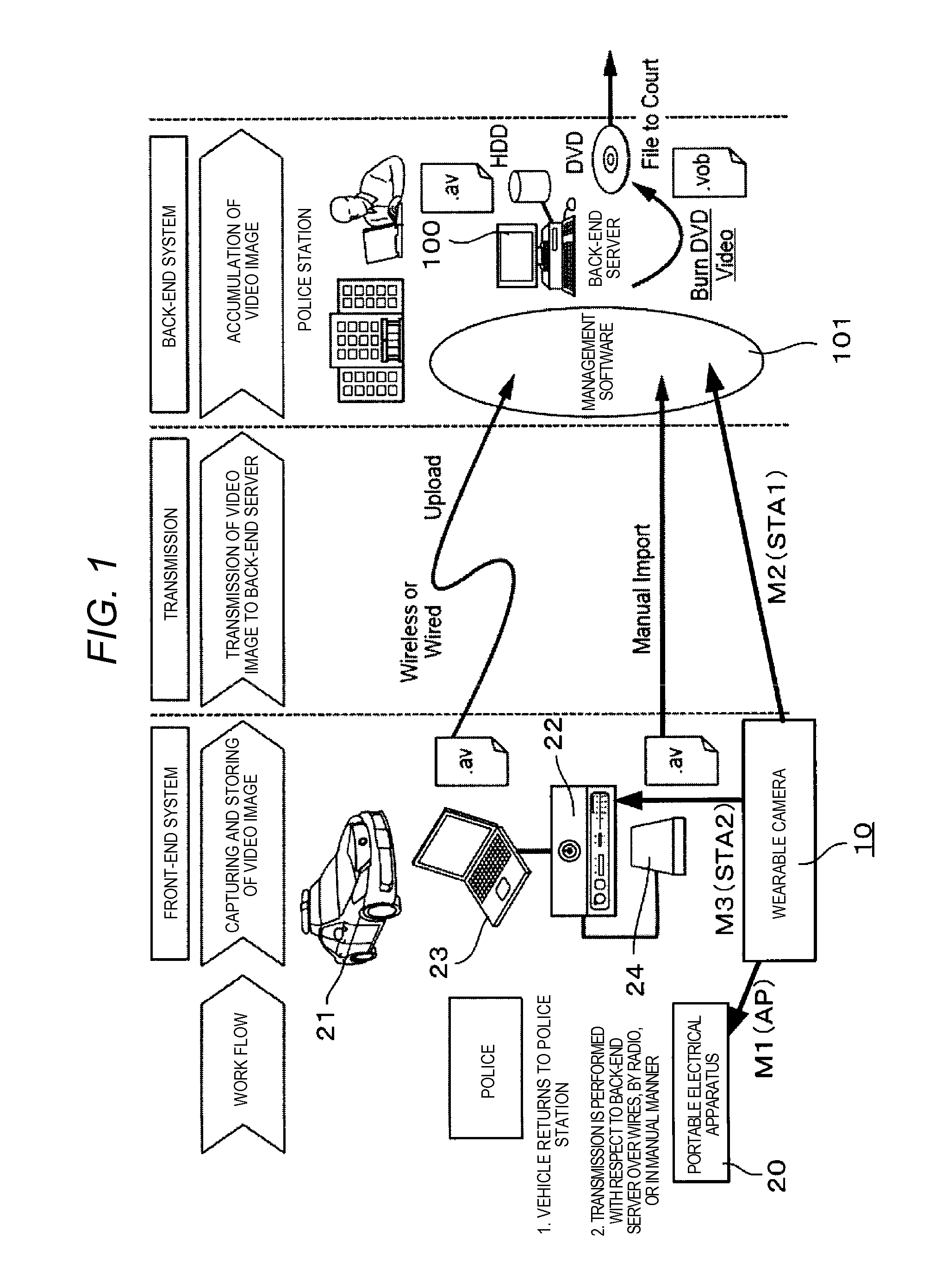
[0029]FIG. 1 is a schematic diagram illustrating an example of an overall image of a wearable camera system which uses wearable camera 10. From the left to the right, the diagram illustrates a front-end system in which wearable camera 10 is directly adopted, transmission in which data is sent from the front-end system, and a back-end system in which transmitted information is processed.

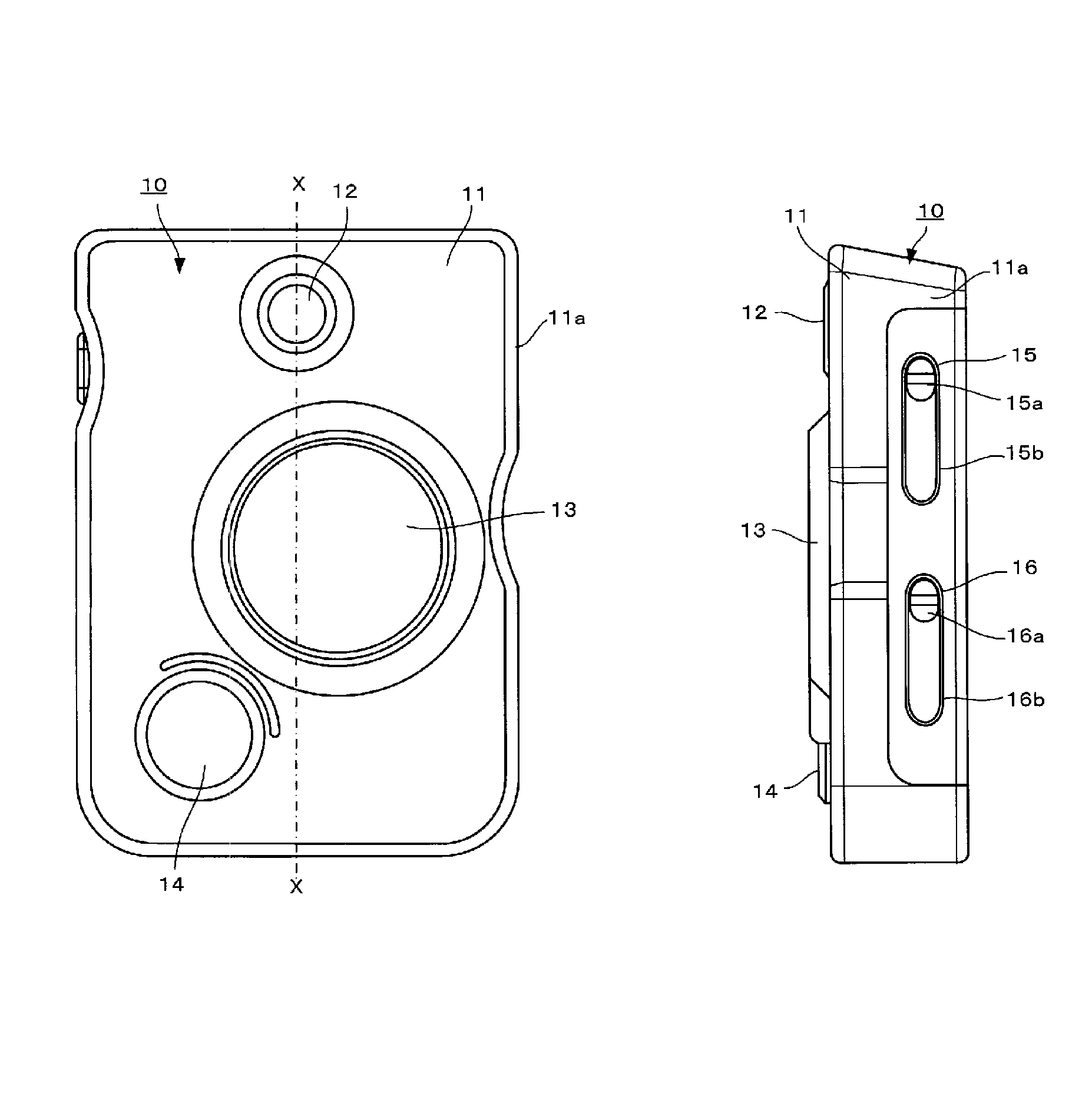
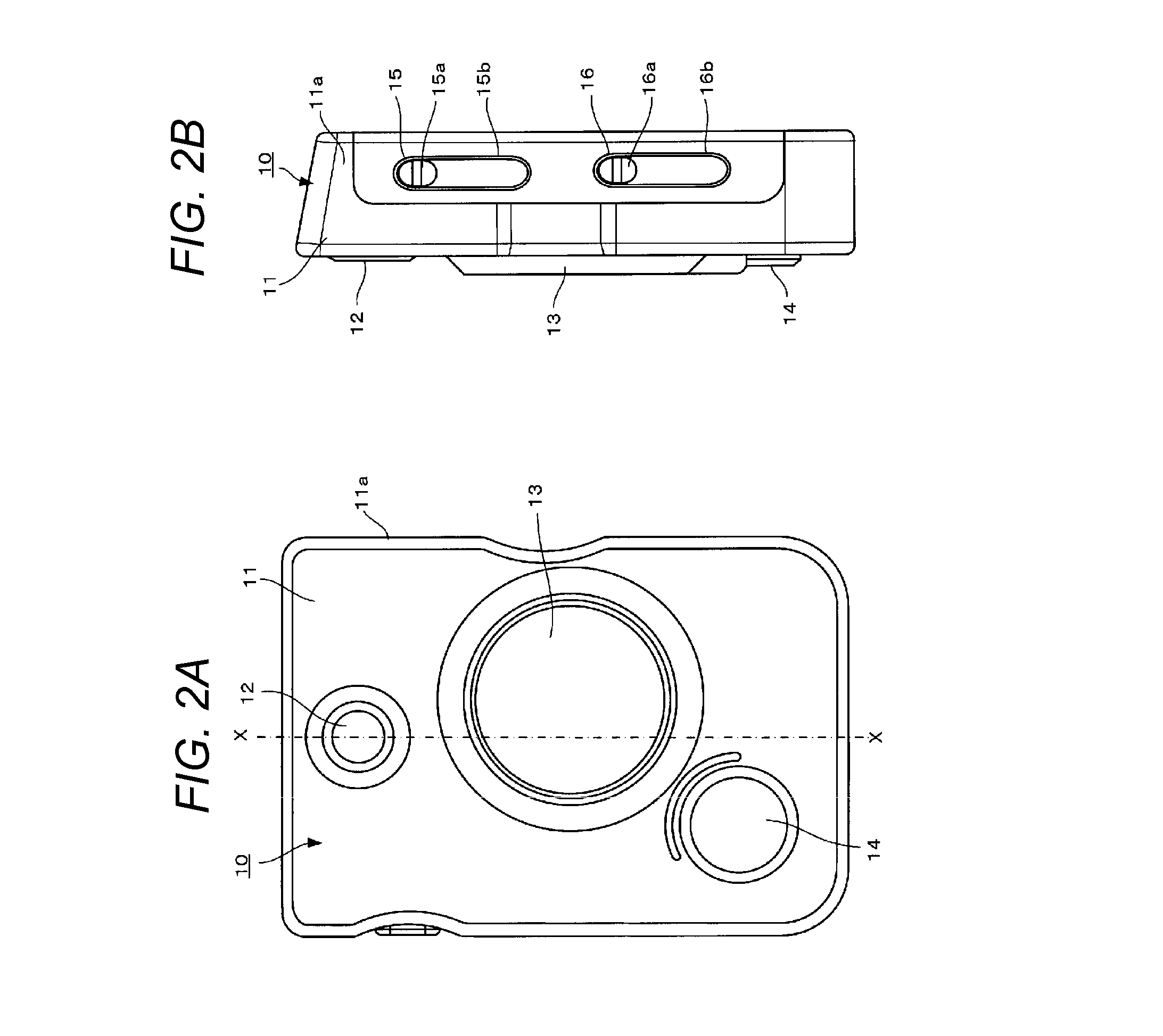
[0030]Wearable camera 10 (WCAM) worn by a police officer that is an example of an operator (a user) is adopted in the front-end system and mainly performs capturing and storing of video images. Particularly, wearable camera 10 is an image capturing device with which a police officer can be equipped in order to acquire and retain evidential video images of the scene in a more unerring manner. The wearable camera system includes wearable c...


PUM


Abstract

A wearable camera includes a body, a lens, a video recording button, a snap shot button, a mode changeover switch, and a confirmation changeover switch. The mode changeover switch includes an operating section and a linear slot in which the operating section moves. A first mode which is a most-frequently-used mode having a high frequency of use in case of emergency is disposed on an upper end side of the slot, and a fourth mode which is an off mode cutting off connection with the outside is disposed on a lower end side thereof.

Description

BACKGROUND OF THE INVENTION[0001]1. Field of the Invention[0002]The present disclosure relates to a wearable camera which is worn by a police officer and the like.[0003]2. Description of the Related Art[0004]In recent years, particularly in the United States, difficulties in verification regarding discharging of gun and the like executed by a police officer, have become a problem. Therefore, in order to image the circumstances of a scene in an emergency situation and to turn the images into verification of the account of the events thereafter, police officers tend to wear a wearable camera. There is a known wearable camera which is carried on oneself and is capable of automatic imaging.[0005]Japanese Patent Unexamined Publication No. 2004-356970 discloses a wearable camera in which when a sound taken by a sound input section is a sound within a predetermined range of sounds while the camera is carried by an image taker, a trigger detector generates a trigger detection signal and ima...

Claims


Application Information

Patent Timeline
Patent Type & Authority Applications(United States)
IPC IPC(8): H04N5/232
CPCH04N5/23293H04N5/23245G03B17/561H04N23/51H04N23/667F16M13/02
Inventor YAMAGUCHI, KAZUHIKOYOKOMITSU, YASUSHITAGAWA, HARUOSAKIGAWARA, MASAYUKI
Owner PANASONIC INTELLECTUAL PROPERTY MANAGEMENT CO LTD
Why Eureka
Try Eureka