Machine for Harvesting Root Crop

a technology for harvesting roots and machines, applied in the direction of digger harvesters, agriculture tools and machines, agriculture, etc., can solve the problems of crop loss and achieve the effect of optimal monitoring position

Active Publication Date: 2016-04-28
GRIMME LANDMASCHFAB
View PDF3 Cites 9 Cited by
  • Summary
  • Abstract
  • Description
  • Claims
  • Application Information

AI Technical Summary

Benefits of technology

[0012]In the longitudinal direction between the longitudinal conveyor and the screening belt conveyor, there is usually a transfer zone (see prior art brochure SF 150 / 170-60) which comprises a belt overlap so that the crop stream is moved “in a line”. In this area, the construction that is improved according to the invention provides the leading functionally modified module that, based on the common transfer zone, can be moved at least sectionwise into a lateral spacing position relative to the second screening belt conveyor. Accordingly, a “spaced-apart” working position of the lifting device in relation to the downstream devices can be achieved.
[0033]Based on the concept of the adjustable complete potato harvesting machine that has a lifting width of more than two rows, it is provided that in the area above the transfer zone a driver's cabin that is supported in the area of the machine frame is provided. In this way, an optimal installation position is predetermined wherein the driver's cabin can be moveable independent of the component groups of the machine frame and the conveying groups secured therein. An optimization of this installation position of the driver's cabin provides that the latter is secured in the area of the support frame supporting the first longitudinal conveyor. Based on the relative pivot movement of component groups in accordance with the invention into the lateral spacing position, it is provided that the driver's cabin advantageously can be moved together with the support frame so that in this way an optimal monitoring position is ensured.

Problems solved by technology

This affects at the same time handling of the system that is to be steered along the field contour because performing a complete lifting process, in particular near the respective edge zones of the field, may be affected by projecting components of the machine and crop loss can thus occur.

Method used


Image

  • Machine for Harvesting Root Crop
  • Machine for Harvesting Root Crop
  • Machine for Harvesting Root Crop

Examples


Embodiment Construction

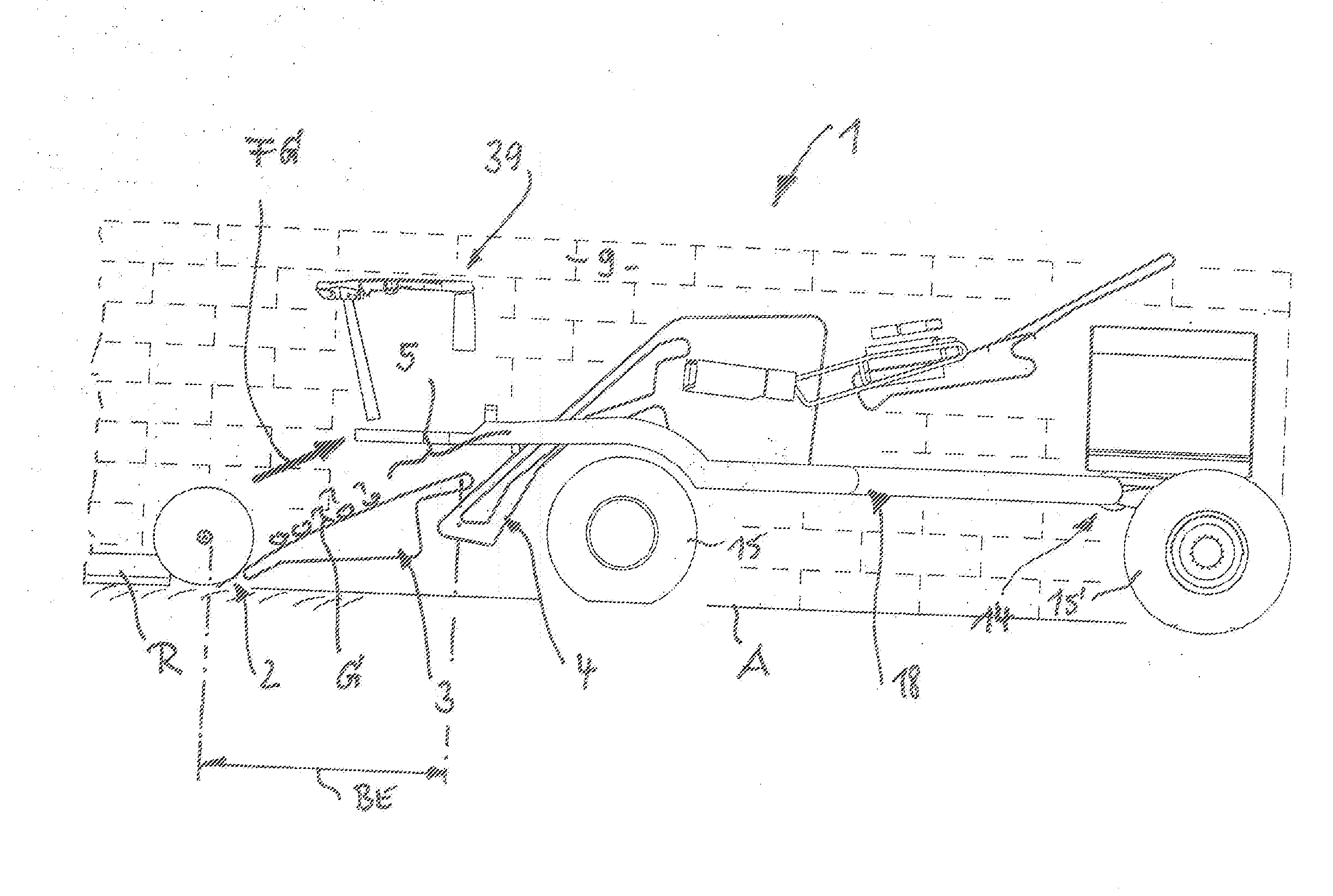
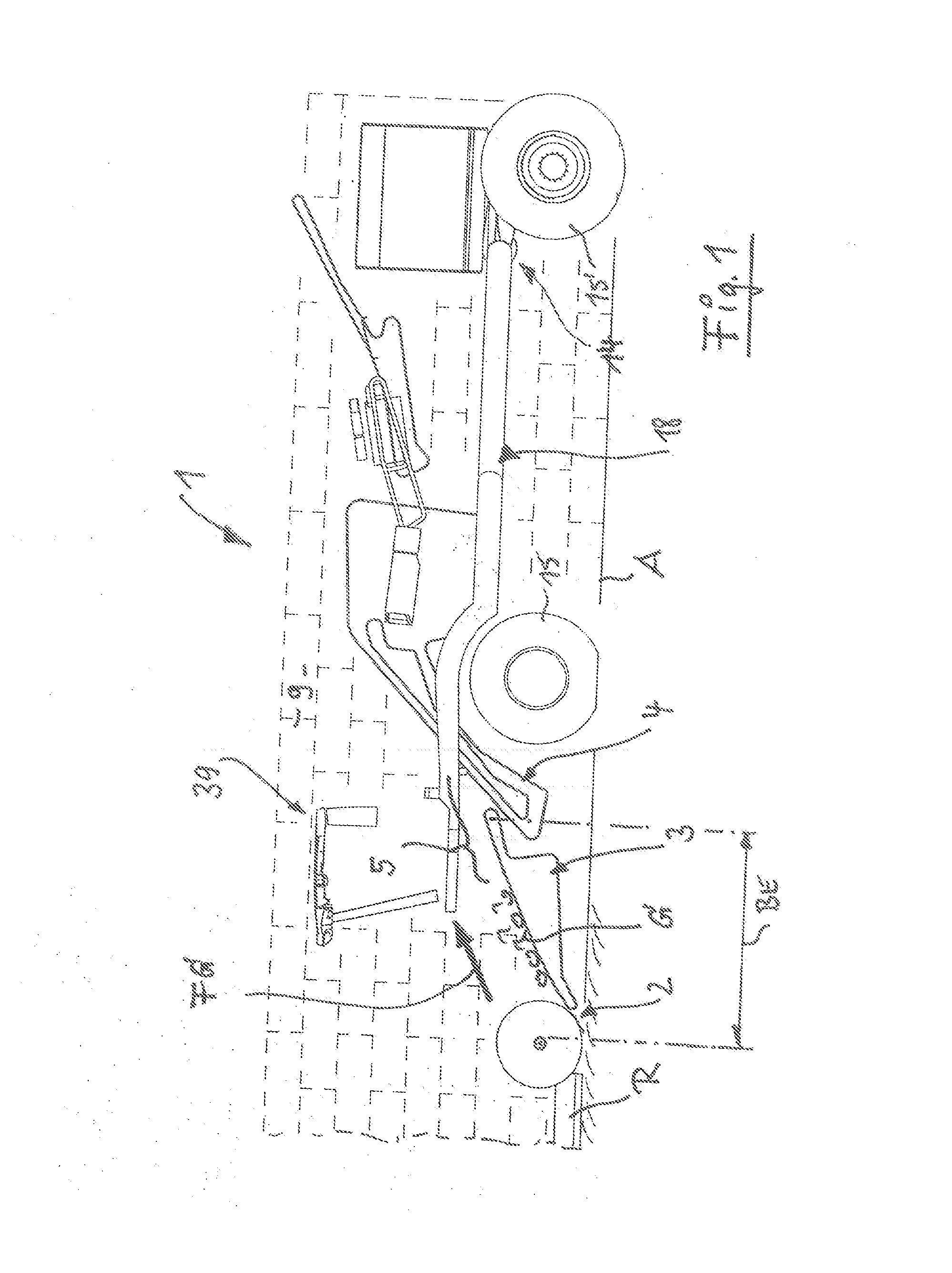
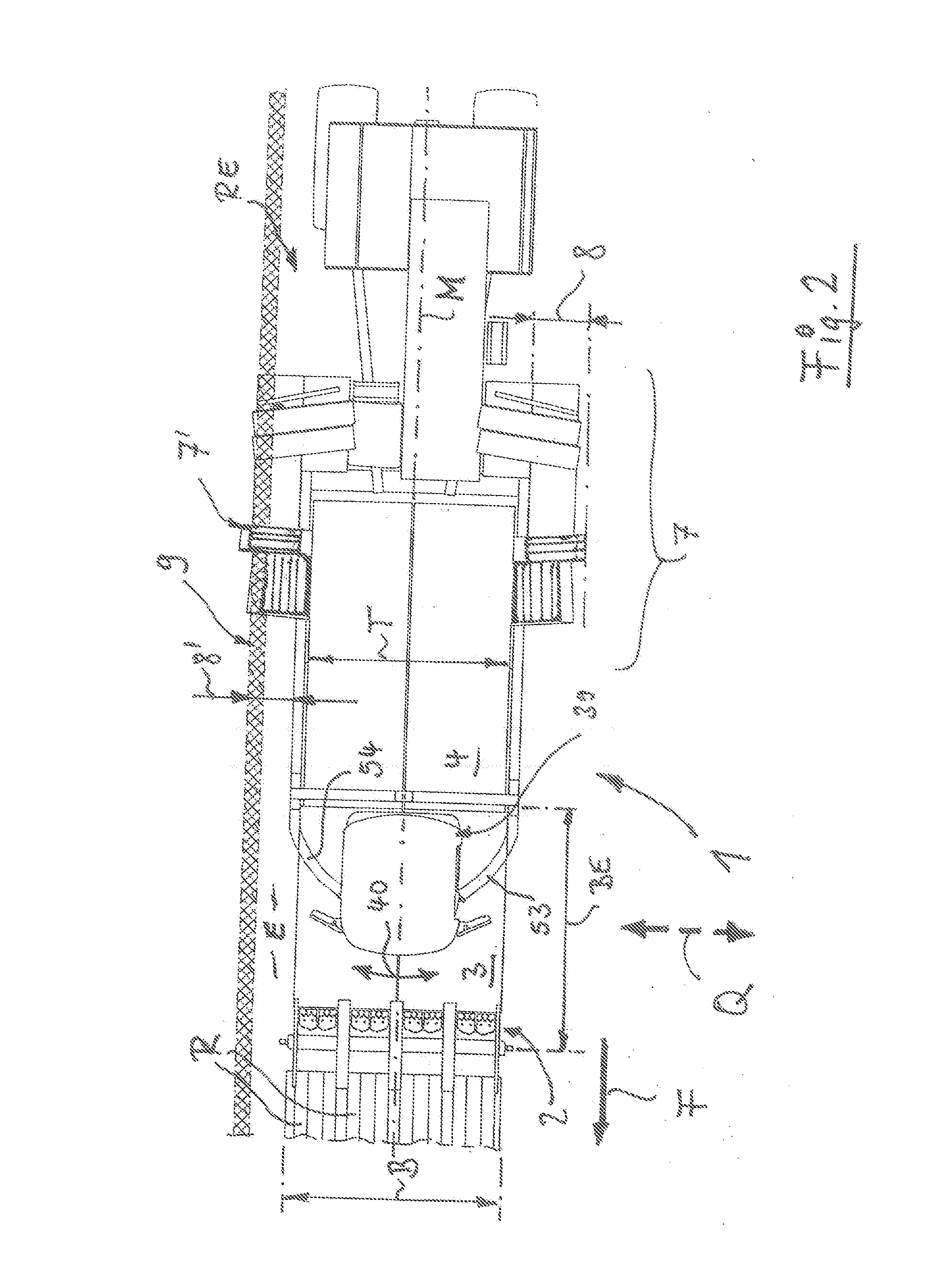
[0050]In the illustrations according to FIG. 1 to FIG. 3, a machine for harvesting root crop, in particular in the form of a complete potato harvesting machine 1, is shown in respective basic illustrations. The side view according to FIG. 1 shows clearly that the construction, by use of generally known component groups, comprises a lifting device 1 that is in the position of use. In this context, on a harvest field E, in accordance with a lifting width B, several rows R of the crop with admixtures are lifted from the soil A transverse to the travel direction F.

[0051]In a self-propelled complete potato harvesting machine as disclosed in the aforementioned brochure SF 150 / 170-60, two rows R are lifted by means of the lifting device 2 and from there the loosened mixture G of crop and admixtures is moved by means of a first longitudinal conveyor 3 opposite to the travel direction F in the conveying direction FG. During the course of this conveying phase, a transfer onto a second screeni...


PUM


Abstract

A machine for harvesting root crop has a lifting device that in a position of use on a harvest field lifts several rows of the crop with admixtures from the soil transversely to the travel direction in accordance with a lifting width. From the lifting device the loosened mixture of crop and admixtures is movable opposite to the travel direction by a first longitudinal conveyor and is transferred onto a second screening belt conveyor. Between longitudinal conveyor and screening belt conveyor, a transfer zone is defined with belt overlap. The first longitudinal conveyor in the conveying direction together with the upstream lifting device forms a module that is movable in transverse direction of the machine relative to the second screening belt conveyor. This module, relative to the common transfer zone, can be moved at least sectionwise into a position of lateral spacing relative to the second screening belt conveyor.

Description

BACKGROUND OF THE INVENTION[0001]The invention concerns a machine for harvesting root crop, in particular in the form of a complete potato harvesting machine; comprising a lifting device that in a position of use on a harvest field lifts several rows of the crop with admixtures from the soil transversely to the travel direction in accordance with a lifting width, wherein from the lifting device the loosened mixture of crop and admixtures by means of a first longitudinal conveyor is movable opposite to the travel direction and is transferred onto a second screening belt conveyor, wherein between longitudinal conveyor and screening belt conveyor a transfer zone is defined that comprises a belt overlap:[0002]Machines for harvesting and processing root crop, in particular potatoes, have been known for a long time in various embodiments of pull-behind devices or self-propelled machines. In such machine configurations, lifting devices that lift several rows of crop with admixtures from th...

Claims


Application Information

Patent Timeline
Patent Type & Authority Applications(United States)
IPC IPC(8): A01D17/00A01D33/00
CPCA01D33/00A01D17/00A01D17/22A01D17/10A01D67/00
Inventor DETTMER, FRANZ-JOSEFFELDKAMPER, STEFAN
Owner GRIMME LANDMASCHFAB
Why Eureka
Try Eureka