Dental implant socket arrangement with annular recess

Active Publication Date: 2016-04-28
STRAUMANN HLDG AG
View PDF7 Cites 1 Cited by
  • Summary
  • Abstract
  • Description
  • Claims
  • Application Information

AI Technical Summary

Benefits of technology

[0015]The dimension and the inclination angle according to the invention of the first tapered section are also advantageous features for the finding of the insertion tool or the abutment during an insertion into an inner bore of the implant. The dimension and the inclination angle of the second tapered section according to the invention provide for advantages for the retention force and the force for the disengagement between the insertion tool and the implant.
[0016]Preferably parts of the first and the second sections of the socket arrangement having an anti-rotational functionality are arranged within a same height along the longitudinal center axis, such that space is saved and the remaining areas of the parts of the first and the second sections remain as large as possible.
[0017]An octagonal cross-sectional arrangement of first contact surfaces of the first sections provides a particularly advantageous aspect of the invention, as the outer surface of an octagon is larger as compared with a surface of a hexagon with a same height. Thus, an octagonal cross-sectional socket with the respective ei

Problems solved by technology

During this screwing operation the problem has to be faced that the insertion tool, which is for instance an Allen wrench engaging with an Allen socket as part of a second section of the socket arrangement, could cause material welding or a deformation within respective lateral second contact surfaces of the Allen socket.
Taking into account the dimensions of a contact area and of a flexible structure with a sma

Method used


Image

  • Dental implant socket arrangement with annular recess
  • Dental implant socket arrangement with annular recess
  • Dental implant socket arrangement with annular recess

Examples


Example

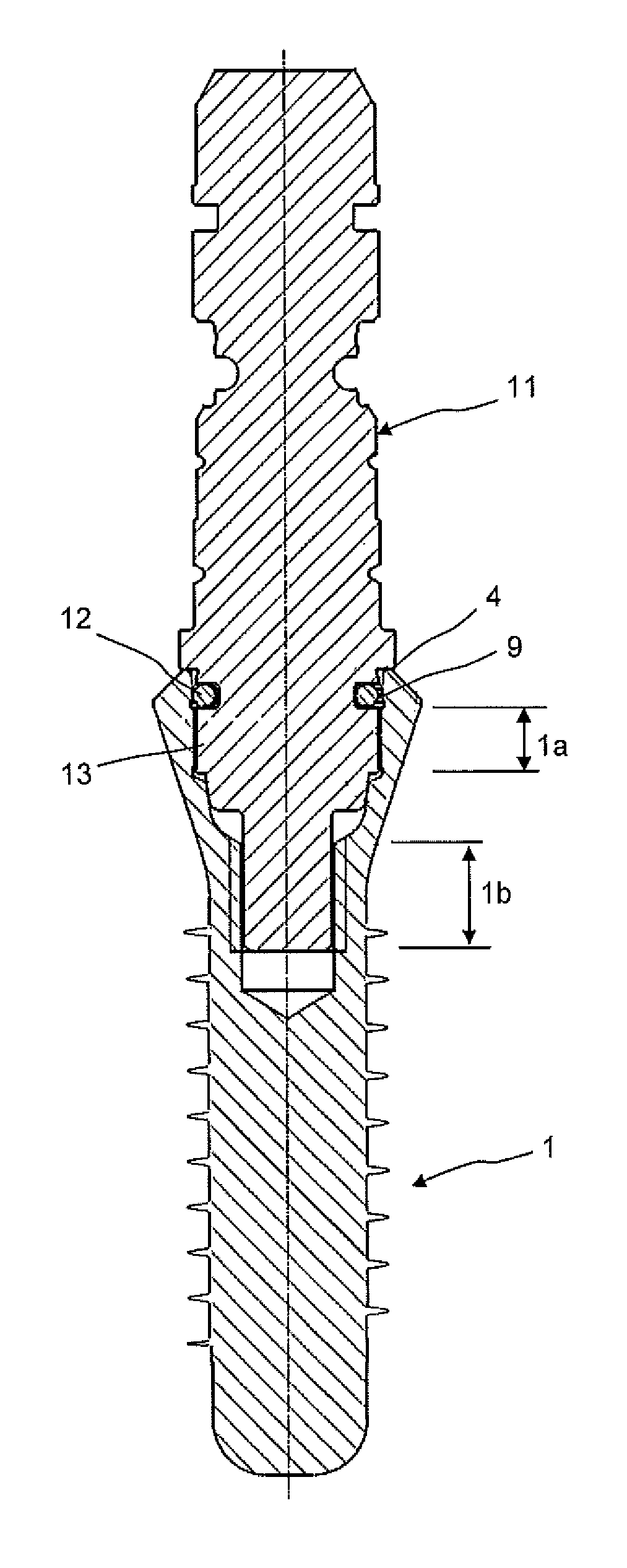
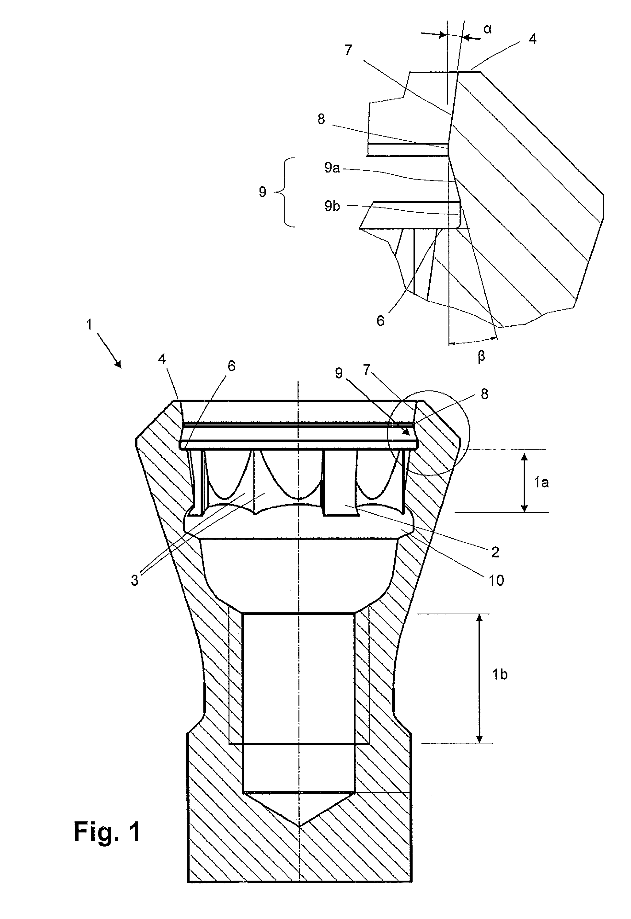
[0025]FIG. 1 shows in a lower part of the figure a cross-sectional side view of a preferred embodiment of a threaded dental implant 1 having an upper annular coronal contact surface 4 being preferably perpendicular to a longitudinal center axis of the implant 1. The upper annular coronal contact surface 4 comprises a centric opening followed by a bore in apical longitudinal direction, wherein the bore along its longitudinal axis is laterally extended by lathing and / or milling. The bore starts, as seen from its coronal end, at the perpendicular annular coronal contact surface 4. Further apically of the contact surface 4 there is provided a first tapered section 7 which is tapered inwardly in apical direction. Preferably the first tapered section 7 is substantially a truncated cone with a first inclination angle. The first tapered section 7 is followed by a first cylindrical section 8, in apical direction. The first cylindrical section 8 is then followed by an annular retention recess...


PUM


Abstract

A threaded dental implant to be screwed into a jawbone for supporting at least one abutment and/or a dental superstructure, and having a socket arrangement with a first section and a second section with respective geometrical profiles around a longitudinal center axis of the implant. The first section cooperates with the abutment for securing the abutment in a determined position in the implant. The second section cooperates with an insertion tool for screwing the implant into the jawbone. The first section includes an annular coronal contact surface on top of an opening centric at a coronal end of the implant, followed in an apical direction by a first tapered section having a diameter decreasing in the apical direction, by a first cylindrical section, by first anti-rotational elements and by a threaded section.

Description

FIELD OF THE INVENTION[0001]The present invention relates in general to a threaded dental implant intended to be screwed into the jawbone for supporting at least one abutment and / or a dental superstructure and in particular to an improved socket arrangement of the dental implant cooperating on the one hand with an insertion tool and on the other hand with the abutment and / or a dental superstructure. Furthermore, the present invention relates to the insertion tool comprising retention means being adapted to engage with a corresponding annular retention recess within the socket arrangement of the implant.PRIOR ART[0002]As known in the art, a threaded dental implant intended to be screwed into the jawbone for supporting at least one abutment and / or a dental superstructure must have a certain socket arrangement with first sections comprising lateral contact surfaces and an upper coronal contact surface and an inner threaded section, such that the abutment can be fixed for a long time in...

Claims


Application Information

Patent Timeline
IPC IPC(8): A61C8/00
CPCA61C8/006A61C8/0069A61C8/0089A61C8/0022A61C8/0066A61C8/0068
Inventor GUENTER, DANIELCOURVOISIER, STEPHANELAZIC, MIODRAGDALLA TORRE, FLORIAN
Owner STRAUMANN HLDG AG
Why Eureka
Try Eureka