Laser surface treatment method and laser surface treatment apparatus with radiating the surface to be treated along an acute angle

Active Publication Date: 2016-04-28
TOYOTA JIDOSHA KK
View PDF5 Cites 4 Cited by
  • Summary
  • Abstract
  • Description
  • Claims
  • Application Information

AI Technical Summary

Benefits of technology

The present invention provides a laser surface treatment method and apparatus for treating a workpiece with an irregular shape. The method and apparatus allow for successful surface treatment without leaving scatters attached to the surface of the workpiece. This is achieved by radiating a laser and performing scanning so that the surface of the workpiece which is placed in a direction forming an acute angle with respect to the laser becomes an untreated plane. The technical effect of this invention is a more precise and efficient laser surface treatment for workpieces with complicated shapes.

Problems solved by technology

However, in the technique described in JP 2008-114252 A, in a case where a surface treatment is performed on a machining target object having an irregular shape, the suction port cannot be brought close around a machining region of the machining target object and a laser cannot be perpendicularly radiated to a surface of the machining target object in some cases.
That is, the technique described in JP 2008-114252 A has such a possibility that the surface treatment cannot be performed successfully on a workpiece (the machining target object).

Method used


Image

  • Laser surface treatment method and laser surface treatment apparatus with radiating the surface to be treated along an acute angle
  • Laser surface treatment method and laser surface treatment apparatus with radiating the surface to be treated along an acute angle
  • Laser surface treatment method and laser surface treatment apparatus with radiating the surface to be treated along an acute angle

Examples


embodiment 1

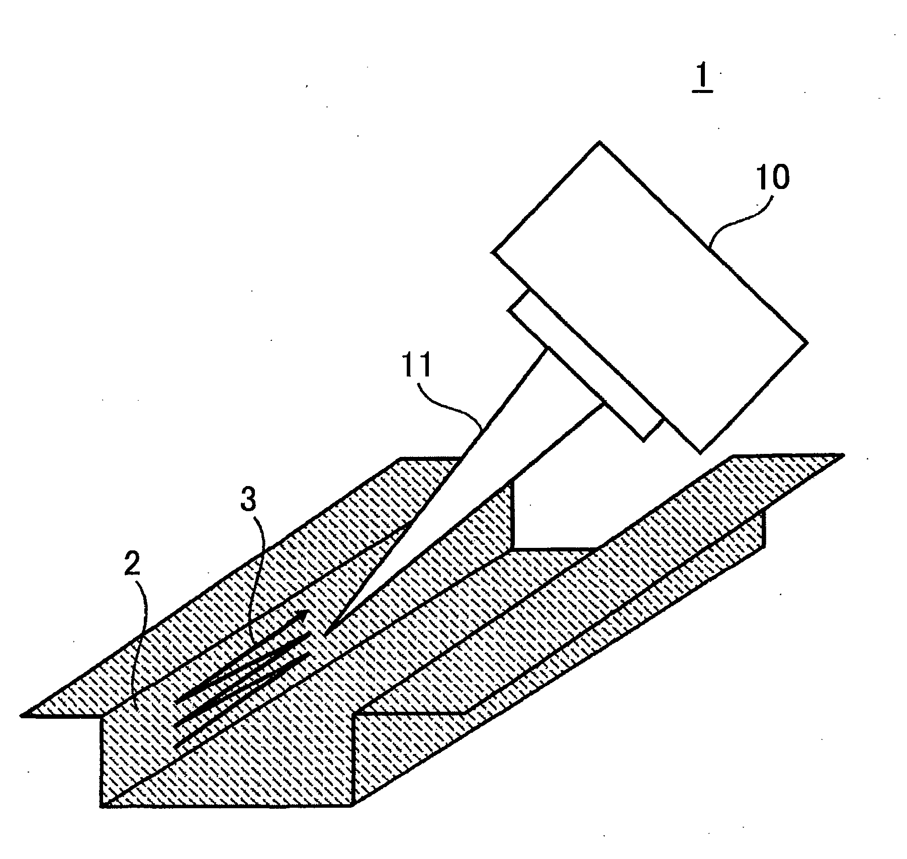
[0035]FIG. 1 is a view illustrating a laser surface treatment apparatus 1 according to Embodiment 1 and a workpiece 2 thereof. The laser surface treatment apparatus 1 according to the present embodiment radiates a laser to perform scanning so that the surface of a workpiece (a machining target object) which is placed in a direction forming an acute angle with respect to the laser becomes an untreated plane; thereby making it possible to successfully perform a surface treatment on the workpiece without leaving scatters attached to the surface of the workpiece. The following describes the laser surface treatment apparatus 1 more specifically.

[0036]The laser surface treatment apparatus 1 illustrated in FIG. 1 includes a scanner 10 that radiates a laser 11 to a surface of the workpiece 2, and a control section (not shown) that controls the scanner 10. The control section controls, for example, a radiation direction of the laser 11 from the scanner 10, and a scanning path 3 of the laser ...

embodiment 2

[0053]The present embodiment deals with a case where a laser surface treatment apparatus 1 performs a treatment on a surface of a workpiece 2 having a recessed R-shape. More specifically, the present embodiment deals with a case where the laser surface treatment apparatus 1 performs a treatment on that surface of the workpiece 2 which has a planar face A1, a planar face A2, and an R portion at a R-shaped corner at which the planar faces A1, A2 intersect with each other.

[0054](First Laser Surface Treatment Method According to Embodiment 2)

[0055]FIG. 8 is a view to describe a first laser surface treatment method according to Embodiment 2.

[0056]Initially, the laser surface treatment apparatus 1 performs a surface treatment on a part of the R portion and the planar face A1 of the workpiece 2 in such a manner that: while performing, from an axis B1 passing through around a center of the R portion, scanning with a laser 11 at a given amplitude in two directions (front and rear directions ...

embodiment 3

[0072]The present embodiment deals with a case where a laser surface treatment apparatus 1 sections a surface of a workpiece 2 into a plurality of treating regions adjacent to each other, and performs a surface treatment in order.

[0073](First Laser Surface Treatment Method According to Embodiment 3)

[0074]FIG. 13 is a view to describe a first laser surface treatment method according to Embodiment 3.

[0075]Initially, the laser surface treatment apparatus 1 defines a shape of a treating region per unit. In an example of FIG. 13, the laser surface treatment apparatus 1 defines the shape of the treating region per unit as a parallelogram in which a vertex on a bottom right in a plane of paper forms an acute angle. Further, in the example of FIG. 13, the laser surface treatment apparatus 1 performs a surface treatment on the treating region per unit in such a manner that: while performing scanning with a laser 11 at a given amplitude in right and left directions in the plane of paper, the ...


PUM

PropertyMeasurementUnit
Angleaaaaaaaaaa
Speedaaaaaaaaaa

Abstract

A laser surface treatment method for treating a surface of a workpiece having an irregular shape includes radiating a laser so that the surface of the workpiece which is placed in a direction forming an acute angle with respect to the laser becomes an untreated plane. The method also includes scanning with the laser so that the surface of the workpiece which is placed in the direction forming an acute angle with respect to the laser becomes an untreated plane.

Description

BACKGROUND OF THE INVENTION[0001]1. Field of the Invention[0002]The present invention relates to a laser surface treatment method and a laser surface treatment apparatus.[0003]2. Description of Related Art[0004]Japanese Patent Application Publication No. 2008-114252 (JP 2008-114252 A) describes a technique to suck out, from a suction port, scatters caused in laser machining so as to prevent the scatters from being attached to a machining target object.[0005]However, in the technique described in JP 2008-114252 A, in a case where a surface treatment is performed on a machining target object having an irregular shape, the suction port cannot be brought close around a machining region of the machining target object and a laser cannot be perpendicularly radiated to a surface of the machining target object in some cases. In view of this, in the technique described in JP 2008-114252 A, there is a possibility that scatters cannot be sucked out sufficiently and the scatters hit that region ...

Claims


Application Information

Patent Timeline
IPC IPC(8): B23K26/03B23K26/08B23K26/16B23K26/362
CPCB23K26/03B23K26/16B23K26/0869B23K26/362C21D9/46B23K26/0006C21D1/09C21D2221/00C21D2221/10B23K26/361B23K26/352B23K2101/18B23K2103/50
Inventor HISADA, KOHEIKAWAKITA, ATSUSHINAKATA, MASAHIROOKURA, JUNICHI
Owner TOYOTA JIDOSHA KK
Why Eureka
Try Eureka