Device for measuring a level in a tank

a technology of level measurement and tank, which is applied in the direction of level indicators, instruments, printing, etc., can solve the problems of continuous sensor, complex and expensive continuous sensor, and difficult sensor implementation, and achieves low cost and easy implementation. , the effect of easy to implement sensor

a technology of level measurement and tank, which is applied in the direction of level indicators, instruments, printing, etc., can solve the problems of continuous sensor, complex and expensive continuous sensor, and difficult sensor implementation, and achieves low cost and easy implementation. , the effect of easy to implement sensor

US20160114590A1Active Publication Date: 2016-04-28DOVER EURO SARL

Image

  • Device for measuring a level in a tank
  • Device for measuring a level in a tank
  • Device for measuring a level in a tank

Examples


Embodiment Construction

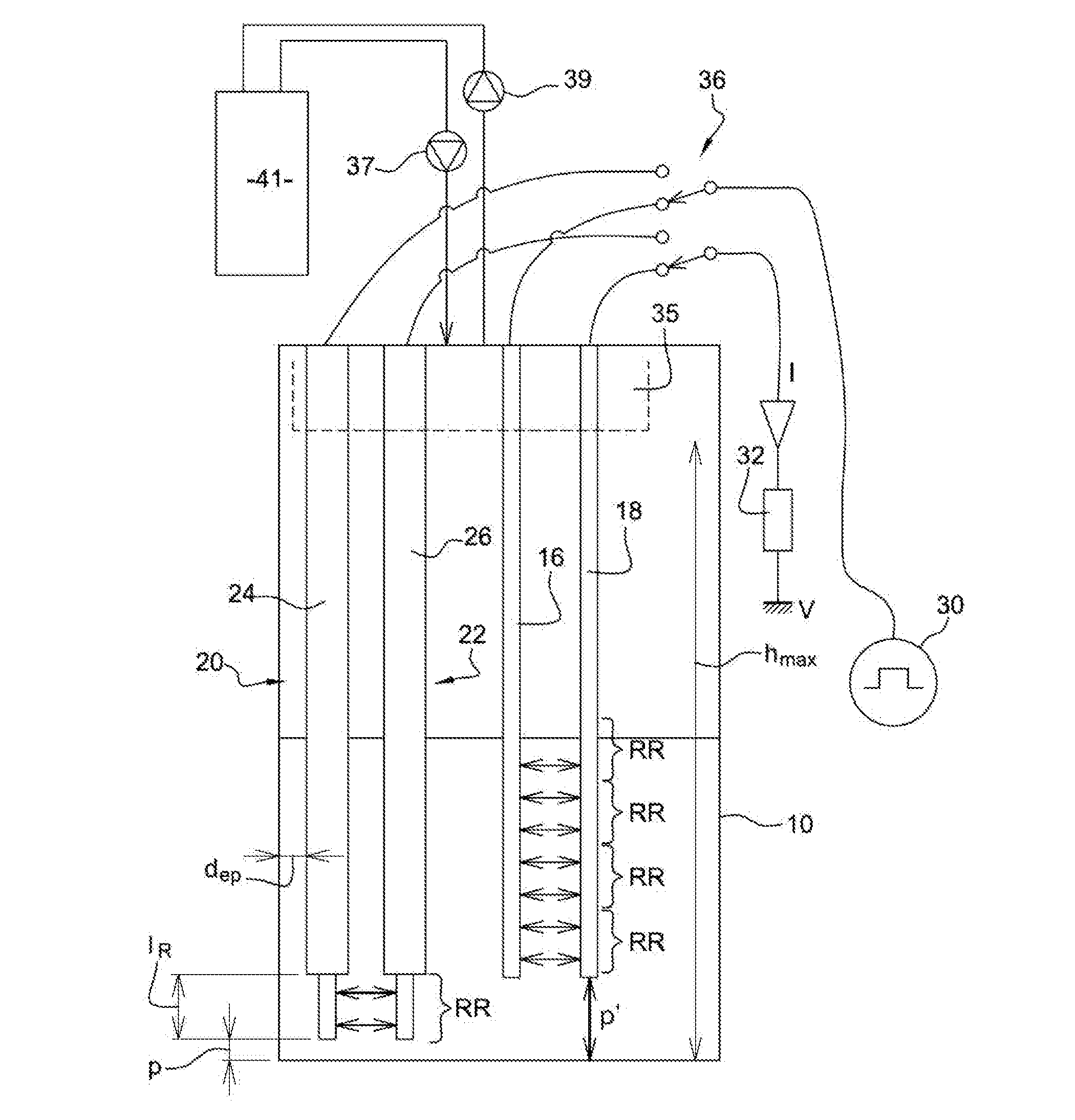
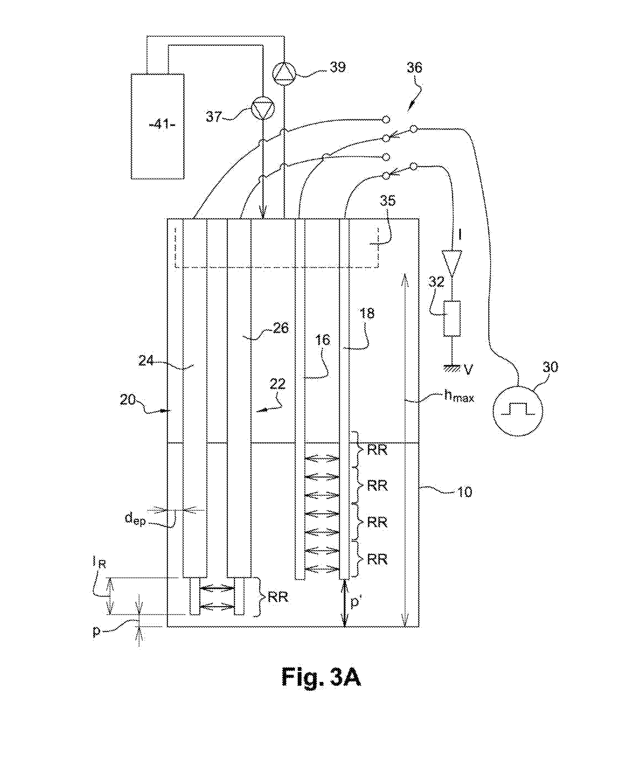
[0098]An example of a measuring device according to the invention is illustrated in FIG. 3A.

[0099]Herein, it is provided in a tank 10.

[0100]It includes 2 conducting rods, or electrodes 16, 18 and 2 reference rods, or electrodes 20, 22.

[0101]Preferably, the reference electrodes are identical to each other and / or the measuring electrodes are identical to each other.

[0102]Each of the reference rods, or electrodes is covered, on most of its length, with a coating, or a sleeve 24, 26, of a dielectric or electrically insulating material, which only allows an end portion (active part) of the corresponding electrode, having a length IR, to project. Thus, it enables a liquid level (or first height), or a signal corresponding to such a liquid level, to be measured or detected, with a depth IR+p, p being the distance between the free end of the reference electrode and the bottom of the tank 2.

[0103]The length IR is preferably determined by a compromise: it is chosen sufficiently great to achie...


PUM


Abstract

A device for continuously measuring a level of an ink in a tank (10) of a continuous ink-jet (CIJ) printer, including: a first pair of electrodes (24, 26) and part for connecting this pair of electrodes in series, for measuring the impedance of a first predetermined height of the ink, in the tank, a second pair of electrodes (16, 18) and part for connecting this second pair of electrodes in series, for measuring a second height of the ink in the tank, this second height being included between this first height and a maximum level; part for calculating the second height, from the resistive components of the 2 impedances measured, independently of the ink conductivity.

Description

TECHNICAL FIELD AND PRIOR ART[0001]The invention relates to the field of continuous ink jet (CIJ) printers.[0002]It also relates to a device and a method for measuring a level of a conducting liquid, in particular ink in a tank of such a printer.[0003]Continuous ink jet (CIJ) printers are well known in the field of industrial coding and labelling for various products, for example to label bar-codes, expiration date on food products, or even references or distance marks on cables or pipes directly on the production line and at a high rate. This kind of printer is also found in some fields of decoration where the graphic printing possibilities of the technology are exploited.[0004]These printers have several standard sub-assemblies as shown in FIG. 1.[0005]First, a printing head 1, generally offset from the body of the printer 3, is connected thereto by a flexible umbilical 2 joining the hydraulic and electrical connections required for operating the head by imparting it a flexibility...

Claims


Application Information

Patent Timeline
28 Apr 2016
Publication
US20160114590A1
IPC
B41J2/175
CPC
B41J2002/17579; B41J2/17566; B41J2/175; G01F23/263; G01F23/266; G01F23/268; G01N27/06
Inventors
ARPIN, JEAN-PIERRE