Solar thermal energy storage system

a technology of solar thermal energy storage and solar energy, which is applied in the field of thermal energy storage systems, can solve the problems of limited disclosure of reservoirs

Active Publication Date: 2016-04-28
STAMICARBON ACTING UNDER THE NAME OF MT INNOVATION CENT
View PDF12 Cites 15 Cited by
  • Summary
  • Abstract
  • Description
  • Claims
  • Application Information

AI Technical Summary

Problems solved by technology

Also, the disclosure related to the reservoirs is limited to thermal storage fluids that are not themselves heated by sol

Method used


Image

  • Solar thermal energy storage system
  • Solar thermal energy storage system
  • Solar thermal energy storage system

Examples


example 1

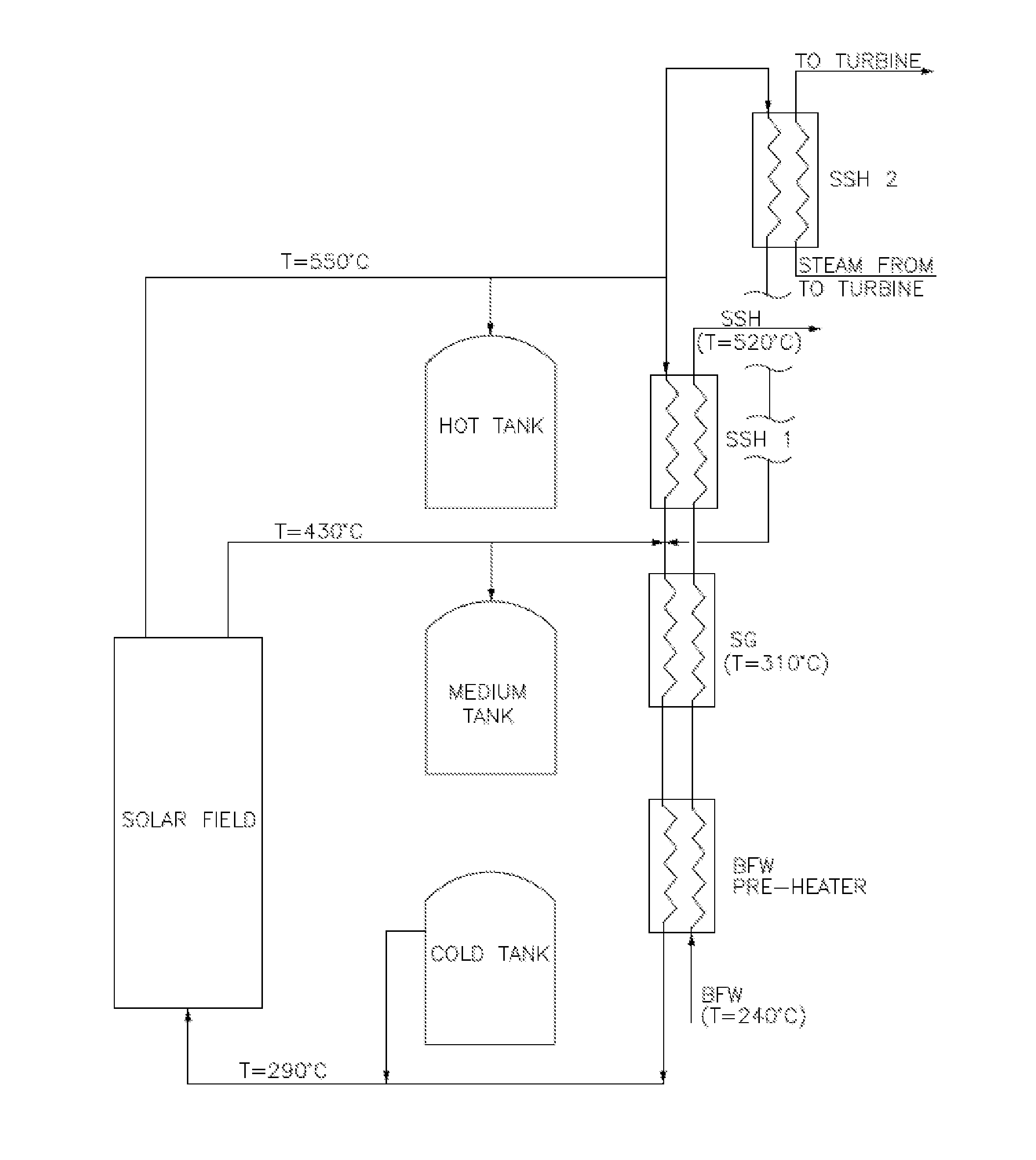
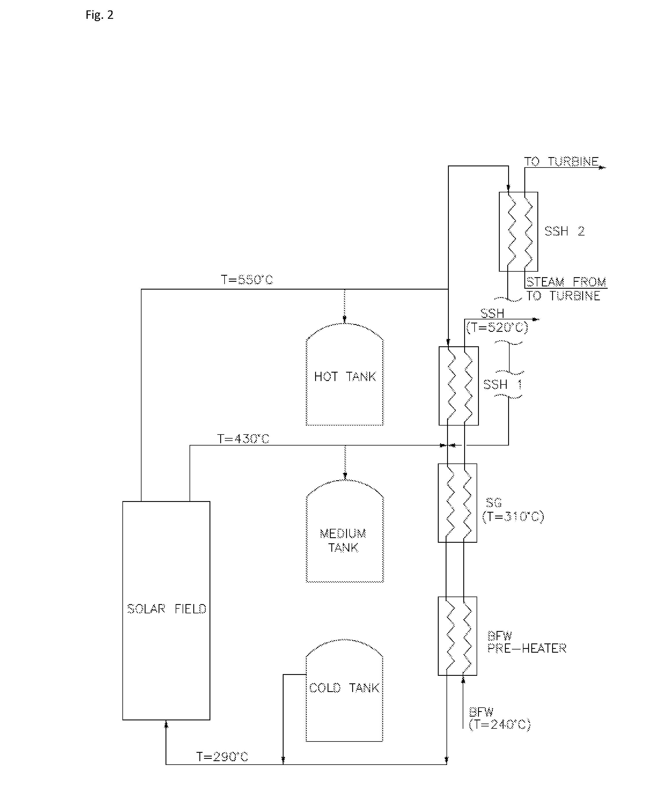
[0060]In FIGS. 2 and 3 is shown an example of a proposed architecture for a solar plant of the invention, with reference to the phases of charging and discharging of molten salt, with and without steam reheating.

[0061]During the charging phase, FIG. 2, the hot MS streams from the solar field at 550° C. are used for:[0062]Filling the hot tank[0063]Superheating the steam, generating the high pressure steam and preheating the BFW[0064]Reheating the steam from the steam turbine (SSH2) meanwhile the 430° C. stream is used for;[0065]Filling the medium temperature tank[0066]Mixing with MS stream carrying from SSH1

[0067]MS circulating in the system is withdrawn from the cold tank where the MS was accumulated at the end of the discharging phase.

[0068]In FIG. 3, the hot MS flows through the SSH exchanger, is then mixed with MS stream at the outlet of SG before the BFW preheater. The MS flow at 450° C. enters the SG boiler where the high pressure steam is raised. After the BFW preheater the co...

example 2

[0071]This example refers to an architecture similar to that of Example 1. Here, however, a back-up boiler (FIG. 4) is provided to have a better control of steam temperature and steam flow to the steam turbine. This will allow to further maximize the Rankine cycle efficiency.

[0072]The back-up boiler typically is a fired heater where MS temperature before the SSH and / or the SG exchangers, is controlled by firing natural gas or any other gas or liquid fuel.

example 3

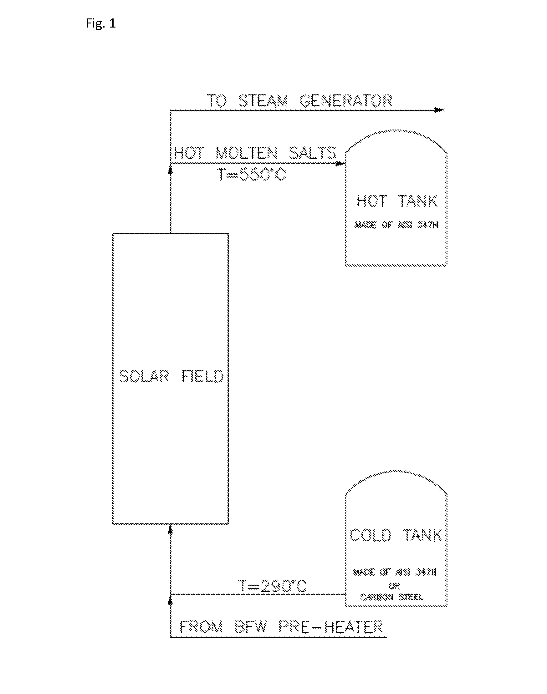
[0073]FIG. 5 shows a different configuration of the invention's architecture with 4 tanks, where two different tanks are used for the SSH purpose allowing to use the more expensive materials (steel grade “347H” in this case) only for the tank indicated as hot / hot tank, with a limited volume. In this case the hot tank is made in 316L and MT tank could be made of C-SA 335 carbon steel for instance. The hot / hot tank operates up to 585° C. Depending on the molten salts chosen, the same concept can also be used with a still higher temperature tank (up to, e.g., 800° C.).

[0074]In the proposed architecture MS streams are withdrawn from the solar field at: 430° C., 480° C. and 550° C., maximizing also the life of the receiver tubes and minimizing the high temperature stress to a small fraction of the Solar Field (SF) and the SF surface. The decoupling of the SSH duty can be also used when there is a need to reheat the steam from the steam turbine before a further subsequent expansion.


PUM


Abstract

Disclosed is a thermal energy storage system for storing collected solar thermal energy. The system comprises a solar thermal energy collection facility in the form of a field of parabolic troughs, which is in thermal communication with a molten salt circuit. The molten salt circuit is in fluid communication with a molten salt storage facility comprising at least three storage tanks that are each in fluid communication with the molten salt circuit. The multiple tanks set-up allows using cheaper materials, and a more efficient storage of thermal energy.

Description

FIELD OF THE INVENTION[0001]The invention pertains to a thermal energy storage system for use in a concentrated solar power plant (CSP plant). Particularly, the invention is in the field of such systems comprising a solar thermal energy collection facility which is in thermal communication with a molten salt circuit, with said molten salt circuit being in fluid communication with a molten salt storage facility. Also, the invention pertains to a solar power plant.BACKGROUND OF THE INVENTION[0002]In CSP plants, solar energy is captured in a concentrated way by means of mirrors, such as a field of parabolic troughs, or a combination of a tower and a field of heliostats. The thus collected solar thermal energy is used to heat a fluid that serves to produce steam which, in turn, is used to produce electric power by means of a turbine and generator system.[0003]It will be understood that sun radiation is not available continuously. Therefore, the thermal energy recovered from solar radiat...

Claims


Application Information

Patent Timeline
IPC IPC(8): F03G6/06F24J2/34
CPCF24J2/34F03G6/065F03G6/067F24S60/10Y02E10/46
Inventor BARSI, ADRIANOIAQUANIELLO, GAETANO
Owner STAMICARBON ACTING UNDER THE NAME OF MT INNOVATION CENT
Why Eureka
Try Eureka