Device for use in the handling of a load and method for producing such a device
a technology for handling devices and load, which is applied in the direction of programmed manipulators, manufacturing tools, transportation and packaging, etc., can solve the problems of long downtime of production plants, comparatively time-consuming refitting of production plants between different gripper tools each designed for specific gripping tasks, and low weight of gripper tools presently used in such production plants. , to achieve the effect of low cost, low weight and flexible adaptability
- Summary
- Abstract
- Description
- Claims
- Application Information
AI Technical Summary
Benefits of technology
Problems solved by technology
Method used
Image
Examples
first embodiment
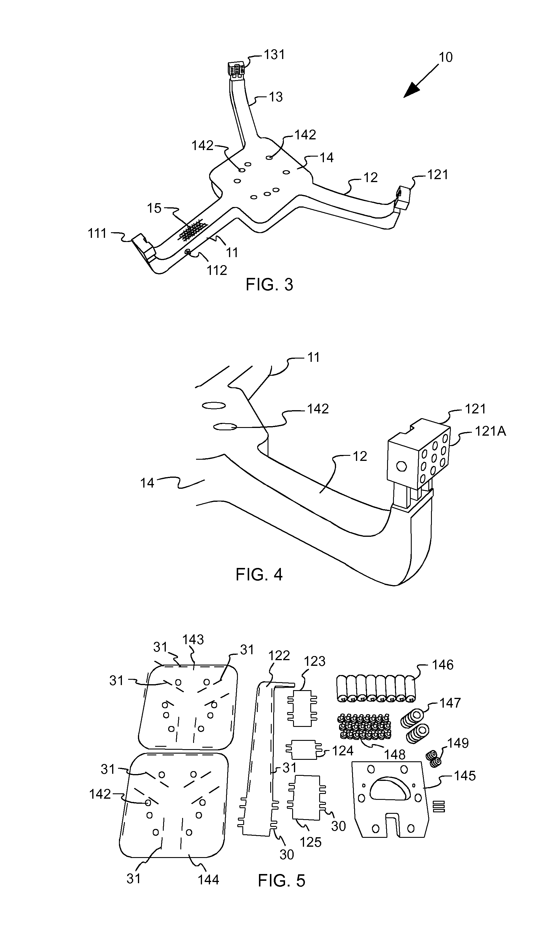
[0071]The single part 124 shown in FIG. 14 has a centering plug unit that comprises in FIG. 14 two straps 30, two noses 32 and a bar 33. The bar 33 is positioned herein between the both straps 30, that means at one of the sides of the straps. One of the noses 32 is positioned on the other side of one strap 30. The noses 32 and the bar 33 each project a little bit out of the edge of the single part 124 as illustrated by the broken lines in FIG. 14. In contrast thereto, the both straps 30 each project many times further out of the edge of the single part 124 than the noses 32. Preferably, the noses 32 and possibly also the bar 33 project out of the edge of the single part 124 so far that they can grip into one through opening 31 of another single part, one single part 122 in this case, however, that they do not project out of the through opening 31 in case the straps 30 are bent, as shown in FIG. 12 in the
[0072]The whole width of the straps 30, the noses 32 and the bars 33 at the edge...
third embodiment
[0074] the centering plug unit does not comprise a bar 33, as shown in FIG. 15. According to a first modification, only one strap 30 is existent herein, at which sides each is positioned one nose 32, as illustrated in FIG. 15 at the left edge of the single part 124. According to a second modification, in fact two straps 30 are existent at which sides each is positioned one nose, as illustrated in FIG. 15 at the right edge of the single part 124. However, the edge of the single part 124 does not project between the straps 30 but is located, for example, on the same straight line like the edge of the single part 124. Alternatively, the edge of the single part 124 located between the straps 30 can also be slotted out of the single part 124 in comparison to the other edge of the single part 124.
fourth embodiment
[0075] the centering plug unit does not comprise noses 32 as shown in FIG. 16 at the left edge of the single part 124. Alternatively, there can also be present only one nose 32 as shown in FIG. 16 at the right edge of the single part 124. In this case, the form-lock between the single parts 122 to 125, 143, 144 for the slip protection is formed by at least the straps 30 and possibly one nose 32.
PUM
| Property | Measurement | Unit |
|---|---|---|
| driving force | aaaaa | aaaaa |
| time | aaaaa | aaaaa |
| weight | aaaaa | aaaaa |
Abstract
Description
Claims
Application Information
 - R&D
- Intellectual Property
- Life Sciences
- Materials
- Tech Scout
- Unparalleled Data Quality
- Higher Quality Content
- 60% Fewer Hallucinations
Browse by: Latest US Patents, China's latest patents, Technical Efficacy Thesaurus, Application Domain, Technology Topic, Popular Technical Reports.
© 2025 PatSnap. All rights reserved.Legal|Privacy policy|Modern Slavery Act Transparency Statement|Sitemap|About US| Contact US: help@patsnap.com


