Brake device for vehicle

a brake device and vehicle technology, applied in the direction of brake systems, braking components, transportation and packaging, etc., can solve the problems of difficult to quickly supply the pressurized operation fluid to the wheel cylinder, and achieve the effect of suppressing the increase of the cost of using (or diverting) the conventional master cylinder and easy formation

Active Publication Date: 2016-05-05
TOYOTA JIDOSHA KK
View PDF5 Cites 6 Cited by
  • Summary
  • Abstract
  • Description
  • Claims
  • Application Information

AI Technical Summary

Benefits of technology

[0027]In this regard, when the connection passages and the bypass passages can be provided corresponding to the brake systems, respectively, for example, a combination of the bypass passage configured to include the atmospheric pressure chamber of the master cylinder described above and the bypass passage configured to include the recirculation passage may be provided. In this manner, the bypass passage is in communication with the reservoir through a different passage and thus, for example, the combination of the bypass passage configured to include the recirculation passage can ensures a redundancy surely, compared with a case that all of the bypass passages are configured to include the atmospheric pressure chamber of the master cylinder, in other words, compared with a case that all of the bypass passages are in communication with the reservoir through the master cylinder. As a result, when the brake pedal is not operated, the pump of the fluid pressure control valve mechanism can suction the operation fluid surely through the bypass passage and supply the pressurized operation fluid to the wheel cylinders to apply braking forces to the vehicle wheels, respectively.
[0028]In this manner, for example, the combination of the bypass passage configured to include the recirculation passage can reduce the number of the bypass passages configured to include the atmospheric pressure chamber of the master cylinder. Thereby, for example, even when the master cylinder conventionally mounted in many vehicles is used (or diverted), the bypass passage can be formed easily and appropriately and the pump of the fluid pressure control valve mechanism can suction the operation fluid smoothly and pressurize the suctioned operation fluid. Therefore, an increasing of a cost for using (or diverting) the conventional master cylinder can be suppressed.
[0029]Further, in these cases, a state of the one-way valve may become a closed state when a spherical valve body seats on a valve seat and become an open state when the valve body displaces away from the valve seat and may be provided such that the valve body seats on the valve seat by the gravity. Thereby, when the driver operates the brake pedal, the fluid pressure control valve mechanism does not suction the operation fluid and thus, the valve body can seat on the valve seat by the gravity to maintain the state of the valve body of the one-way valve at the closed state. Therefore, when the brake pedal is operated and the power-driven type fluid pressure source adjusts the pressure of the operation fluid to supply the operation fluid to the fluid pressure control valve mechanism, the one-way valve, the state of which is maintained at the closed state, can prevent the operation fluid surely from flowing to the side of the master cylinder through the bypass passage.
[0030]On the other hand, when the driver does not operate the brake pedal, the pump of the fluid pressure control valve mechanism suctions the operation fluid and thus, the valve body of the one-way valve can displace away from the valve seat against the gravity by the suction force of the pump to change the state of the valve body to the open state. Therefore, when the pump of the fluid pressure control valve mechanism suctions the operation fluid from the reservoir, the operation fluid can flow smoothly toward the fluid pressure control valve mechanism through the one-way valve under the open state and the bypass passage.

Problems solved by technology

In this case, even when a state of the master cut valve is maintained at an open state, a flow resistance is large when the operation fluid passes through a valve part and as a result, it is difficult for the pump of the VSA device to smoothly suction and thus, it may be difficult to quickly supply the pressurized operation fluid to the wheel cylinders.

Method used


Image

  • Brake device for vehicle
  • Brake device for vehicle
  • Brake device for vehicle

Examples


first embodiment

a. First Embodiment

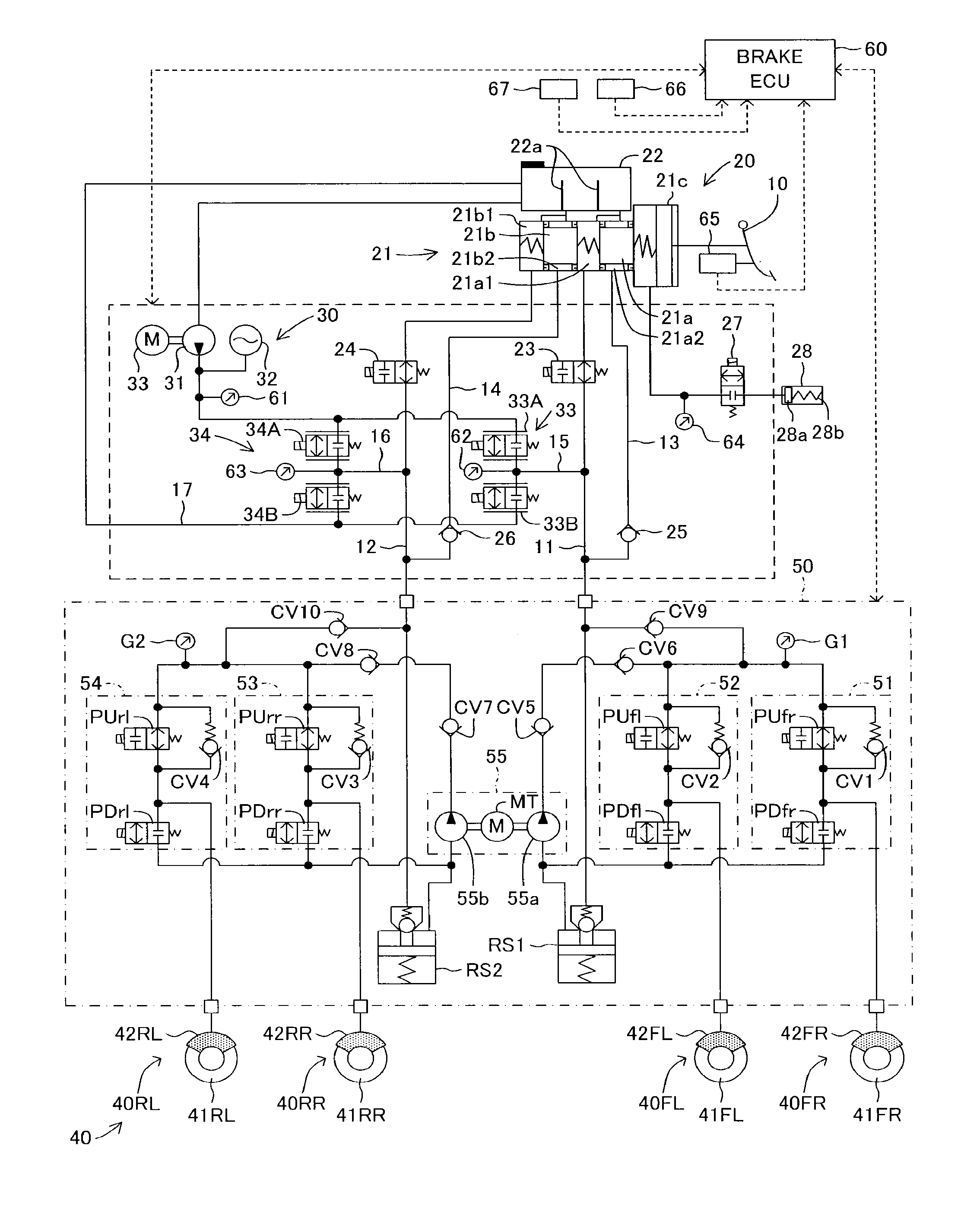
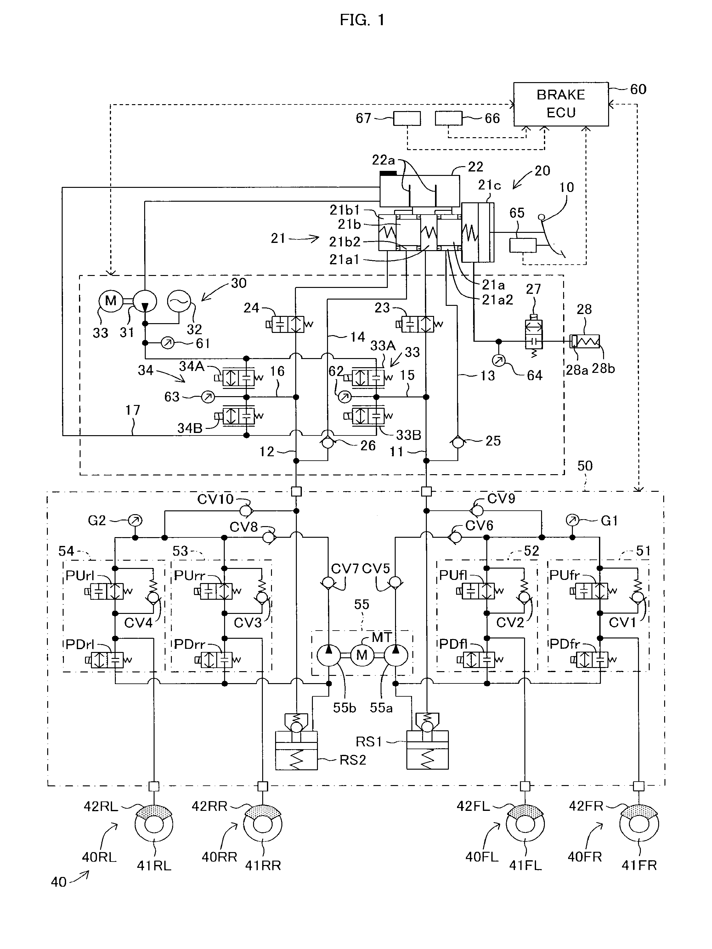
[0040]Below, with reference to the drawings, a brake device for a vehicle according to embodiments of the present invention will be described. FIG. 1 illustrates a schematic system view of a brake device for a vehicle according to a first embodiment. The brake device for the vehicle is configured to include a brake pedal 10, a master cylinder unit 20 serving as a regenerative actuator, a brake fluid pressure generation device 30 serving as a regenerative actuator, a brake unit 40, a brake fluid pressure control valve device 50 serving as a brake fluid pressure control actuator and a brake ECU 60 for managing a brake control.

[0041]The master cylinder unit 20 includes a master cylinder 21 and a reservoir 22. As illustrated in FIG. 1, the master cylinder 21 is a tandem type master cylinder having pressurizing pistons 21a and 21b. The master cylinder 21 includes a brake booster 21c. A pedal depression force input to the brake booster 21c by a depression operation of t...

second embodiment

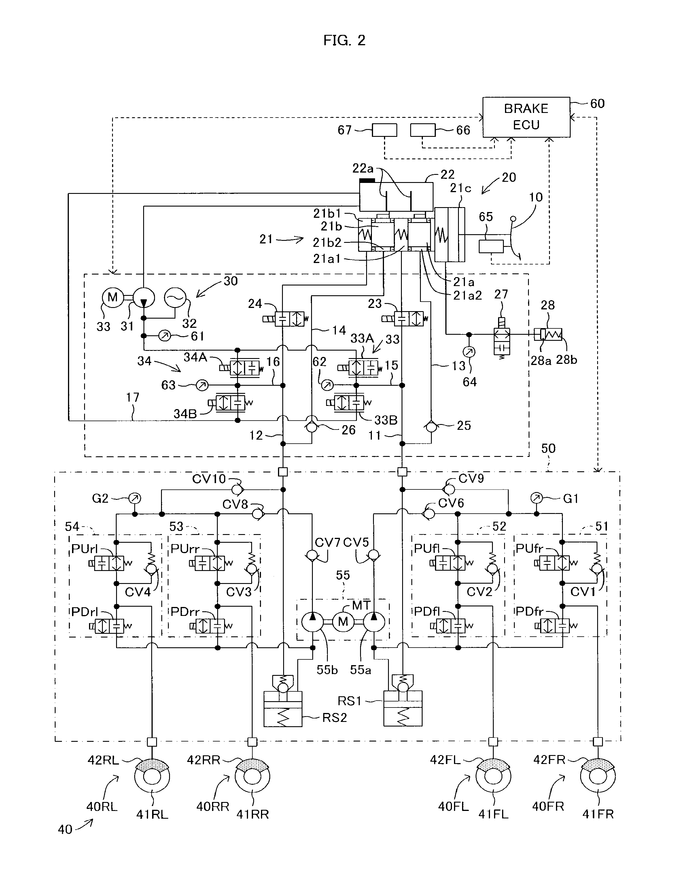
b. Second Embodiment

[0098]According to the first embodiment, the bypass pipe routes are formed by the bypass pipes 13 and 14 and the check valves 25 and 26, which connect the bypass pipes 13 and 14 to the master pressure pipes 11 and 12, respectively. Thereby, according to the first embodiment, the reservoir 22 is in communication with the brake fluid pressurizing section 55 of the brake fluid pressure control valve device 50 through two atmospheric pressure chambers 21a2 and 21b2 formed in the master cylinder 21 of the master cylinder unit 20, the bypass pipes 13 and 14 and the check valves 25 and 26. Therefore, according to the first embodiment, the pumps 55a and 55b of the brake fluid pressurizing section 55 can suction the brake fluid from the reservoir 22 of the master cylinder unit 20 through the check valves 25 and 26 and can pressurize the suctioned brake fluid, thereby to supply the pressurized brake fluid (or the brake fluid pressure) to the upstream sides of the FR and FL...


PUM


Abstract

A master cylinder includes pressurizing chambers and atmospheric pressure chambers which are in communication with a reservoir provided upstream. The pressurizing chambers of the master cylinder are connected to a brake fluid pressure control valve device through master pressure pipes provided with master cut valves. The atmospheric pressure chambers of the master cylinder bypass the master cut valves and are connected to the brake fluid pressure control valve device through bypass pipes provided with check valves. A pump constituting a brake fluid pressurizing section of the brake hydraulic control valve device suctions the brake fluid from the reservoir preferentially through the bypass pipes provided with the check valves and pressurizes the brake fluid to supply a brake fluid pressure to brake fluid pressure adjust sections.

Description

TECHNICAL FIELD[0001]The present invention relates to a brake device for a vehicle, comprising:[0002]a master cylinder for generating a fluid pressure depending on an operation of a brake pedal by a driver;[0003]a power-driven type fluid pressure source for generating a fluid pressure by a drive using a predetermined power and supplying a fluid pressure adjusted depending on the operation of the brake pedal;[0004]a reservoir for reserving an operation fluid, the reservoir being in communication with upstream sides of the master cylinder and the power-driven type fluid pressure source;[0005]wheel cylinders for applying braking forces to vehicle wheels of the vehicle, respectively downstream of the master cylinder and the power-driven type fluid pressure source;[0006]a fluid pressure control valve mechanism for independently controlling fluid pressures in the wheel cylinders by activation of open-and-close valves and pumps, the fluid pressure control valve mechanism being provided bet...

Claims


Application Information

Patent Timeline
Patent Type & Authority Applications(United States)
IPC IPC(8): B60T13/68B60T13/66B60T13/14B60T13/58B60T7/04
CPCB60T13/686B60T13/58B60T13/662B60T13/146B60T7/042B60T8/38B60T8/4081B60T2270/604
Inventor NIMURA, KAZUNORINAKAOKA, HIROSHI
Owner TOYOTA JIDOSHA KK
Why Eureka
Try Eureka