Spoiler for an Aircraft Bay

Inactive Publication Date: 2016-05-05
THE BOEING CO
View PDF3 Cites 15 Cited by
  • Summary
  • Abstract
  • Description
  • Claims
  • Application Information

AI Technical Summary

Benefits of technology

[0012]Another embodiment of the present disclosure provides an aircraft airflow management system comprising a group of frames and louvers. The group of frames are configured to move between a stowed position in a bay of the aircraft and an active position outside the bay of the aircraft. The louvers are physically associated with the group of frames. The louvers are configured to change an airflow relativ

Problems solved by technology

When the doors of the weapons bay are open during flight, the airflow does not move over the aircraft in a desired manner.
Instead, the opening of the doors often results in an unstable airflow that buffets aircraft structures, the payload, or both.
The vortices remain on the aft wall of the cavity causing vibrations.
The vibrations may cause undesired noise in the weapons bay.
For example, the vibrations may result in high levels of resonance and acoustic levels within the weapons bay.
These vibrations may adversely affect the structures or parts of the aircraft such that the aircraft does not perform in a desired manner.
An undesired noise may reduce performance characteristics such as stealthiness of the aircraft and may result in needed aircraft structures that have increases in wei

Method used


Image

  • Spoiler for an Aircraft Bay
  • Spoiler for an Aircraft Bay
  • Spoiler for an Aircraft Bay

Examples


Embodiment Construction

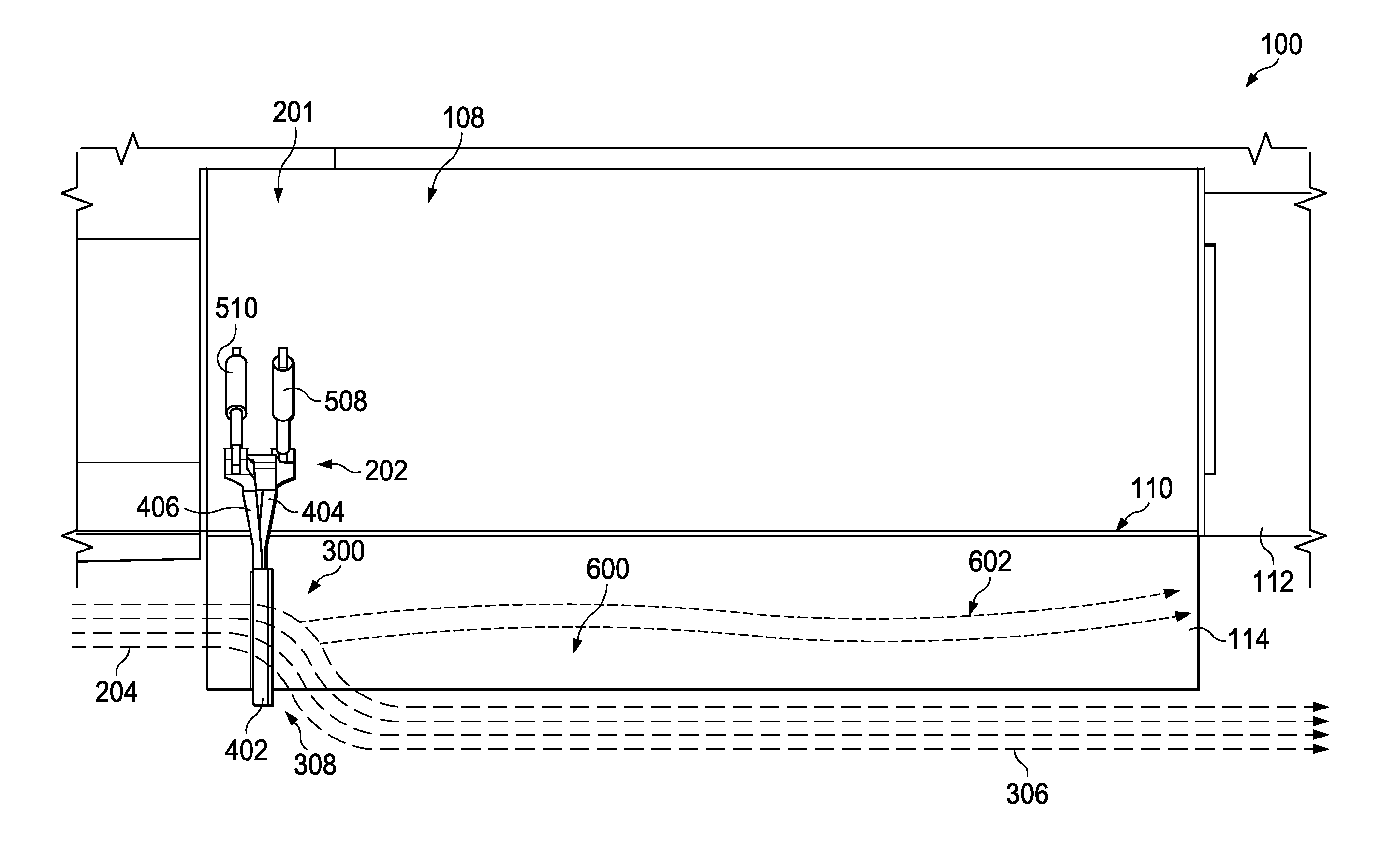
[0033]The illustrative embodiments recognize and take into account one or more different considerations. For example, the illustrative embodiments recognize and take into account that currently used devices introduced into an airflow moving past a bay in an aircraft often cause more turbulence than desired. The illustrative embodiments also recognize and take into account that currently used spoilers are static in design. In other words, the illustrative embodiments recognize and take into account that a spoiler for the bay of an aircraft may be designed to take into account the characteristics of the bay and the payload.

[0034]The illustrative embodiments recognize and take into account that a spoiler designed for a particular bay and payload may not perform as well in reducing undesired airflow when placed in a different bay. Further, even when used in the same bay, when the payload is changed, the spoiler may not reduce undesired airflow as much as desired.

[0035]Further, the illus...


PUM


Abstract

A method for managing an airflow of an aircraft. A spoiler is moved into the airflow passing a bay of the aircraft when the bay is open. The airflow moving relative to the bay is changed to form a desired airflow using louvers physically associated with a frame system in the spoiler.

Description

BACKGROUND INFORMATION[0001]1. Field[0002]The present disclosure relates generally to aircraft and, in particular, to an airflow management system. Still more particularly, the present disclosure relates to a method and apparatus for managing an airflow moving past a bay in an aircraft[0003]2. Background[0004]Many types of aircraft have one or more bays that may open during different phases of flight. For example, military aircraft may have a weapons bay on the underside of the fuselage of the military aircraft. The weapons bay may be a cavity or a space inside the military aircraft that is covered by one or more doors. The weapons bay allows for the deployment of a payload located within the weapons bay. The payload may be, for example, equipment, stores, munitions, other types of payload.[0005]When the doors of the weapons bay are closed, the surface of the aircraft has a desired shape and smoothness that enhances aerodynamic performance as well as other characteristics of the air...

Claims


Application Information

Patent Timeline
IPC IPC(8): B64C5/12B64C23/00
CPCB64C23/005B64C5/12B64C2220/00B64C9/326B64C23/06B64D1/06Y02T50/10Y02T50/40
Inventor EVEKER, JAMES VINCENTHUHMAN, PATRICK DALECRITES, CINDY LEE
Owner THE BOEING CO
Why Eureka
Try Eureka