
Dual-mode plug nozzle

Inactive Publication Date: 2016-05-05
GENERAL ELECTRIC CO
View PDF6 Cites 11 Cited by
  • Summary
  • Abstract
  • Description
  • Claims
  • Application Information

AI Technical Summary

Benefits of technology

The invention provides a nozzle for a gas turbine engine with an increased throat area and a movable inner and outer shroud for controlling the fluid flow through the nozzle. The centerbody, inner and outer shrouds, and the outer shroud's forward and aft edges define the nozzle's throat area and exit area. The inner and outer shrouds can be selectively moved forward or aft to adjust the throat area and the exit area ratio. The nozzle allows for greater control over the gas turbine engine's fluid flow.

Problems solved by technology

Historically, the wide range of values for A8 has resulted in degraded performance at some flight conditions.
Fixed nozzles do not kinematically change their geometry and thus do not operate efficiently over a wide range of nozzle pressure ratios (P8 / Pamb).
Because of the overlapping flap and seal structure, leakage paths may be created which reduce operating efficiency.
Furthermore, for a number of engine cycles, the scheduled A9 / A8 area ratio versus A8 relationship will not provide an optimum match to the engine cycle demands.
As a result, such engines will not deliver peak nozzle performance at certain key operating points.
Despite attempts in the prior art to provide overlapping flap and seal nozzles seeking to enable independent A9 and A8 control, the prior art nozzles continue to suffer from excessive complexity and sealing difficulties.
However, for systems wherein the engine cycle demands two vastly different nozzle pressure ratios at a given nozzle throat area A8; such as for example not meant to be limiting, P8 / Pamb=2.5 at one flight condition and P8 / Pamb=20.0 at another flight condition, both conditions retaining nearly the same value for A8, the nozzle of such systems will not be able to attain a geometry that will provide desired performance for operation at both flight conditions.

Method used


Image

  • Dual-mode plug nozzle
  • Dual-mode plug nozzle
  • Dual-mode plug nozzle

Examples


Embodiment Construction

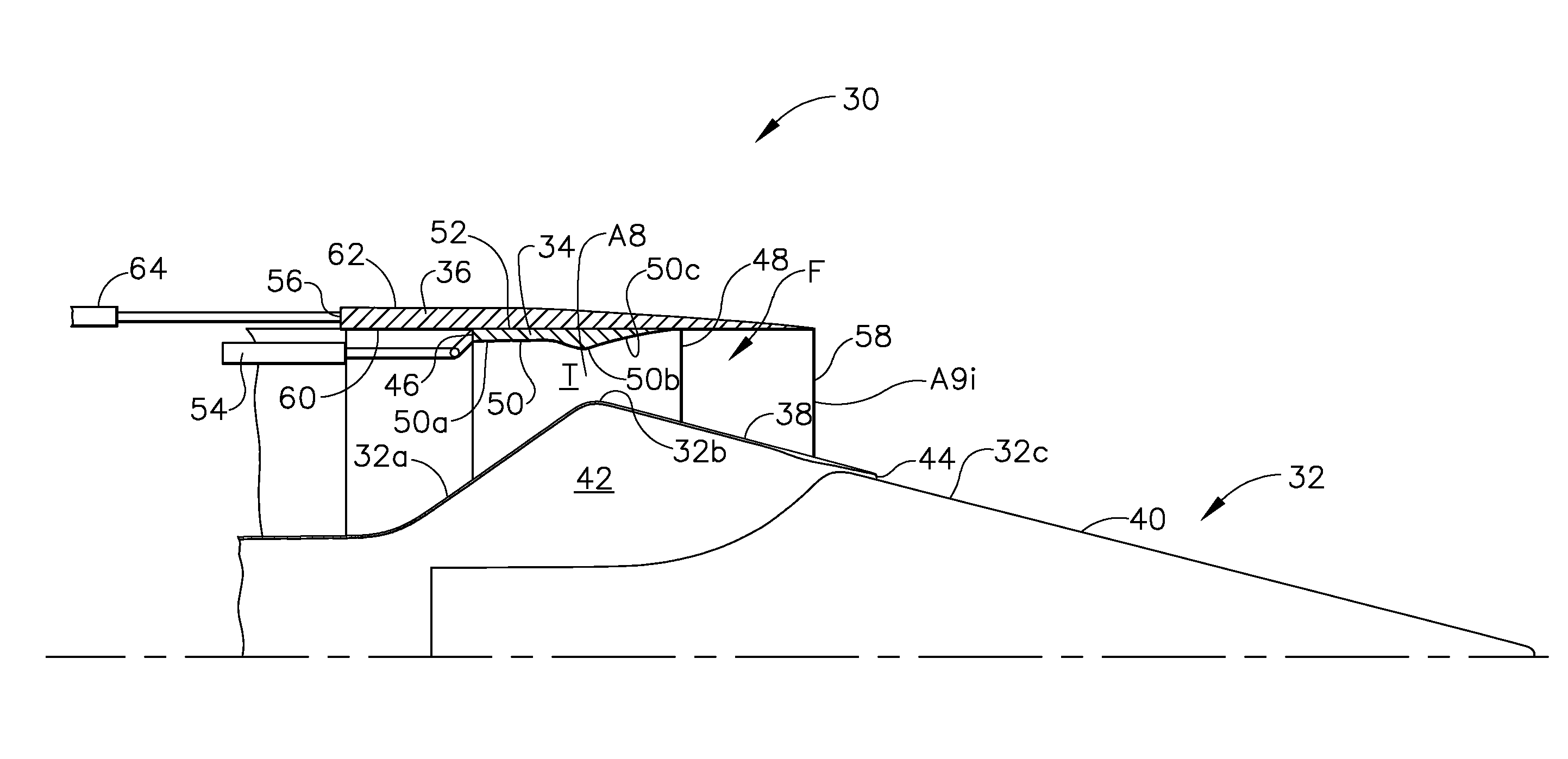
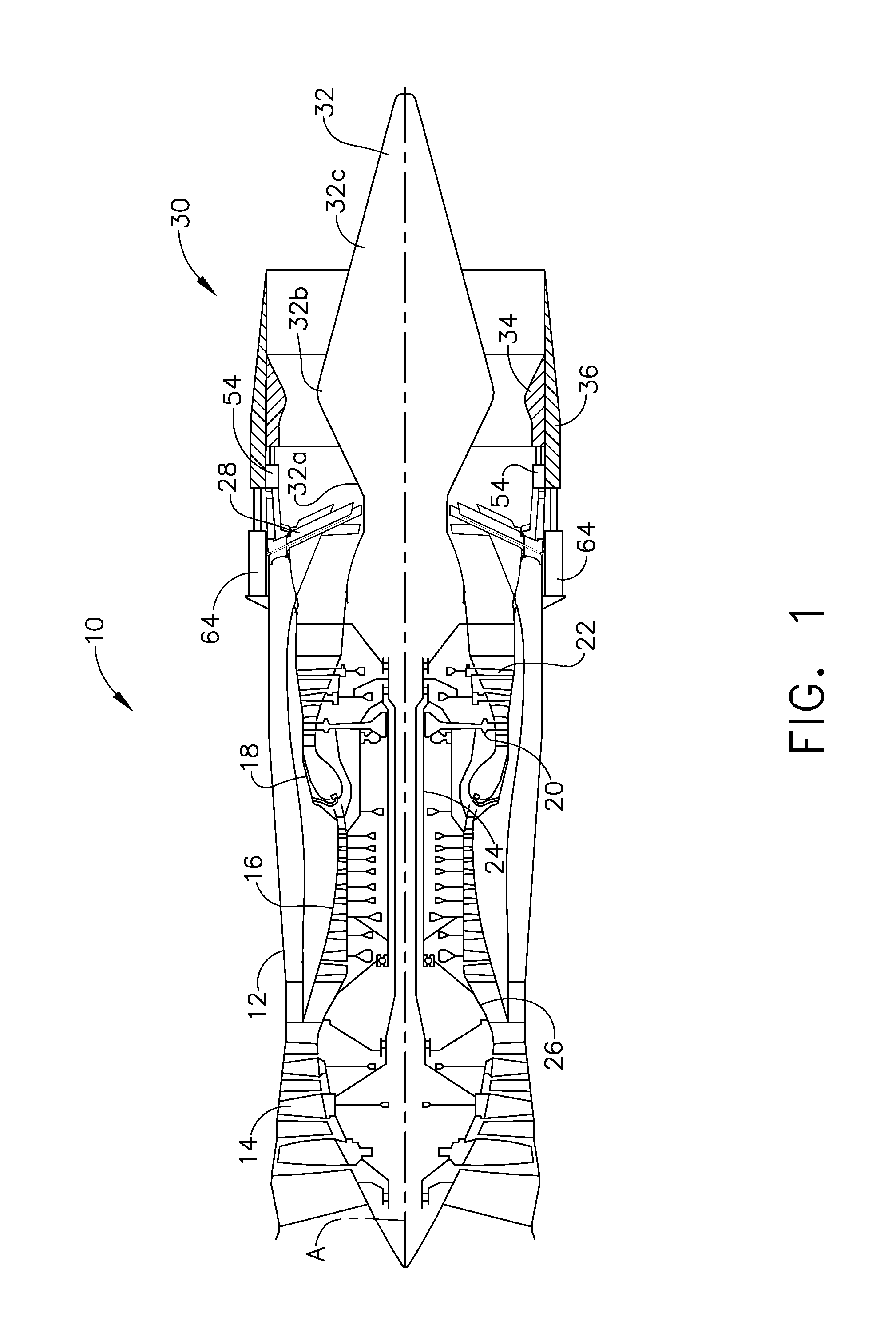
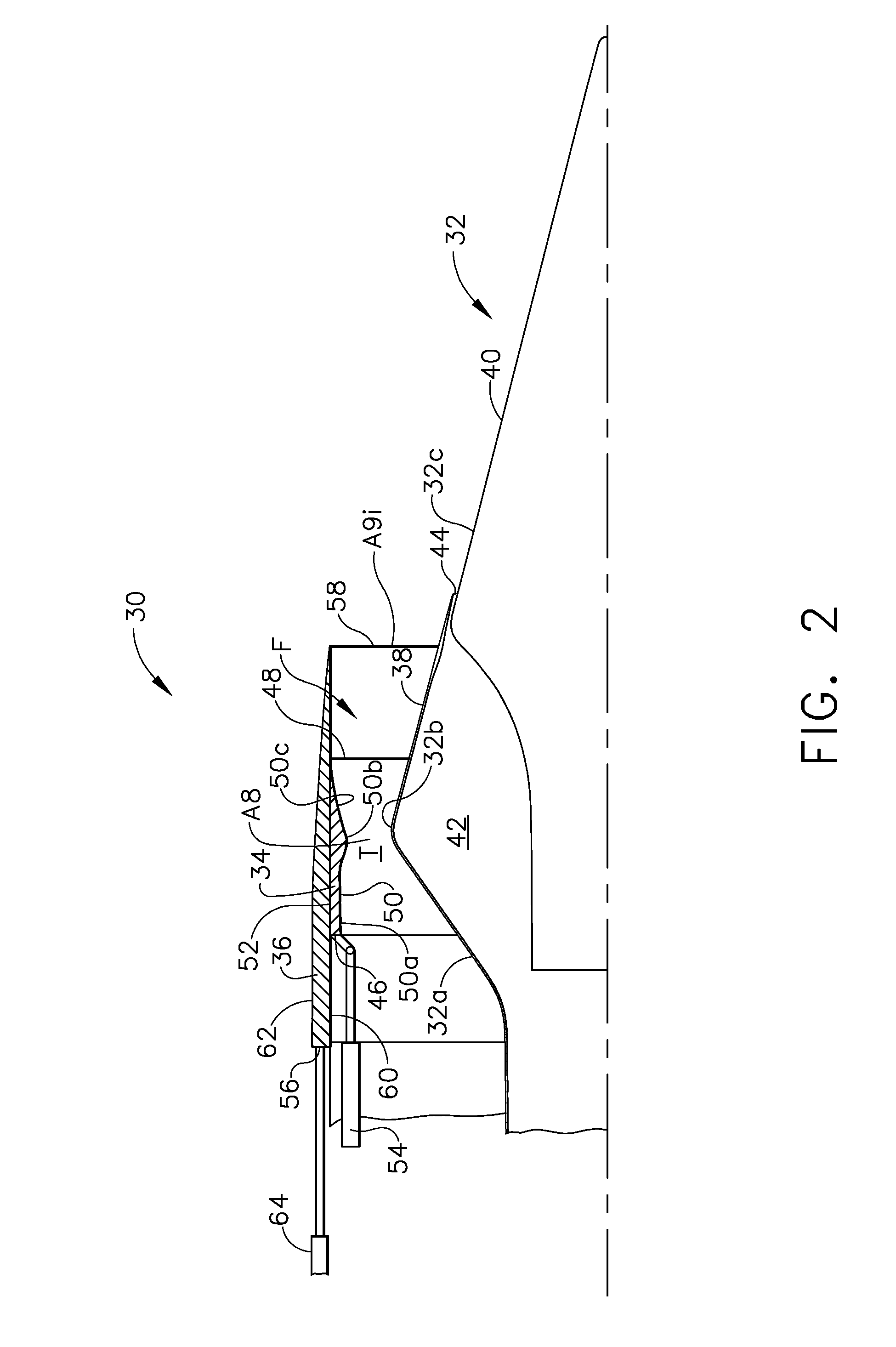
[0022]Reference now will be made in detail to embodiments provided, one or more examples of which are illustrated in the drawings. Each example is provided by way of explanation, not a limitation of the disclosed embodiments. The present embodiments apply to the gas turbine engine, for example aeronautical, power generation, industrial or marine, in which a combustor burns fuel and for which aircraft operation in the supersonic flight regime is intended. Embodiments herein utilize current plug nozzle technology to include the use of existing linear actuators. The embodiments provide the ability to further optimize nozzle performance over all flight conditions.

[0023]Present embodiments relate to engines for supersonic aircraft. In particular, engines intended for operation in supersonic flight require a large variability in nozzle throat area (A8), with associated dimensional units for area typically selected from a group of at least m2, in2 or ft2), nozzle exit area (A9), and area r...


PUM


Abstract

A variable geometry convergent-divergent nozzle for a gas turbine engine includes a centerbody extending rearward along a longitudinal axis of the engine which has a maximum diameter section. An inner shroud surrounds the centerbody and cooperates with the centerbody to define the throat of the nozzle. An outer shroud surrounds the inner shroud and cooperates with the centerbody to define the exit area of the nozzle. Both shrouds are independently translatable to provide independent control of the nozzle throat area and the nozzle expansion ratio. Additional actuation of the inner shroud results in the throat being disposed upon a fully forward portion of the centerbody, said fully forward shroud disposition being more forward than over the maximum diameter section. The nozzle may further comprise independent translation of the centerbody with respect to the shrouds.

Description

CROSS-REFERENCE TO RELATED APPLICATIONS[0001]This application is a national stage application under35 U.S.C. §371(c) of prior filed, co-pending PCT application serial number PCT / US2014 / 39914, filed on May 29, 2014 which claims priority to U.S. Patent Application Ser. No. 61 / 829,495, titled “Dual-Mode Plug Nozzle” and having filing date May 31, 2013, all of which is incorporated by reference herein.[0002]The US Government may have certain rights in this invention pursuant to Contract No. MDA972-01-3-0002 (DARPA) awarded by the US Department of Defense.BACKGROUND[0003]Embodiments of the present invention relates generally to nozzles for gas turbine engines and more particularly to a variable geometry nozzle which functions as a convergent nozzle, a divergent nozzle or a convergent-divergent nozzle.[0004]Variable geometry is required where exhaust systems for gas turbine engines operate over a wide range of pressure ratios (i.e. nozzle throat pressure / ambient pressure or P8 / Pamb) where...

Claims


Application Information

Patent Timeline
IPC IPC(8): F01D17/14F01D9/02
CPCF01D17/14F05D2240/128F05D2220/32F01D9/02F02K1/08F05D2250/41F02K1/09Y02T50/60
Inventor TERSMETTE, TREVOR ANDREWLEE, JASON ADAM
Owner GENERAL ELECTRIC CO
Learn More