Rotating machine with at least one active magnetic bearing and spaced auxiliary rolling bearings

Active Publication Date: 2016-05-05
NUOVO PIGNONE TECH SRL
View PDF10 Cites 5 Cited by
  • Summary
  • Abstract
  • Description
  • Claims
  • Application Information

AI Technical Summary

Benefits of technology

[0009]It is an object of embodiments of the present invention to provide a rotating machine having auxi

Problems solved by technology

Failure or insufficient normal operation of the active magnetic bearings may sometimes occur with an interruption of the electrical power supply.
Failure may also occur in the event of excessive loads applied on the rotor assembly.
However, with such ball bearings, the number of landing phases which can be sustained wi

Method used


Image

  • Rotating machine with at least one active magnetic bearing and spaced auxiliary rolling bearings
  • Rotating machine with at least one active magnetic bearing and spaced auxiliary rolling bearings
  • Rotating machine with at least one active magnetic bearing and spaced auxiliary rolling bearings

Examples


Example

[0024]The following detailed description of the embodiments refer to the accompanying drawings. The same reference numbers in different drawings identify the same elements.

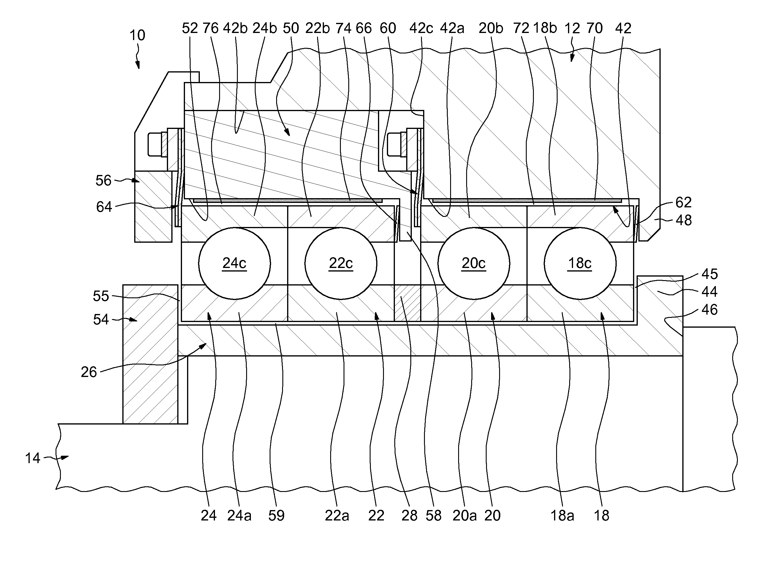
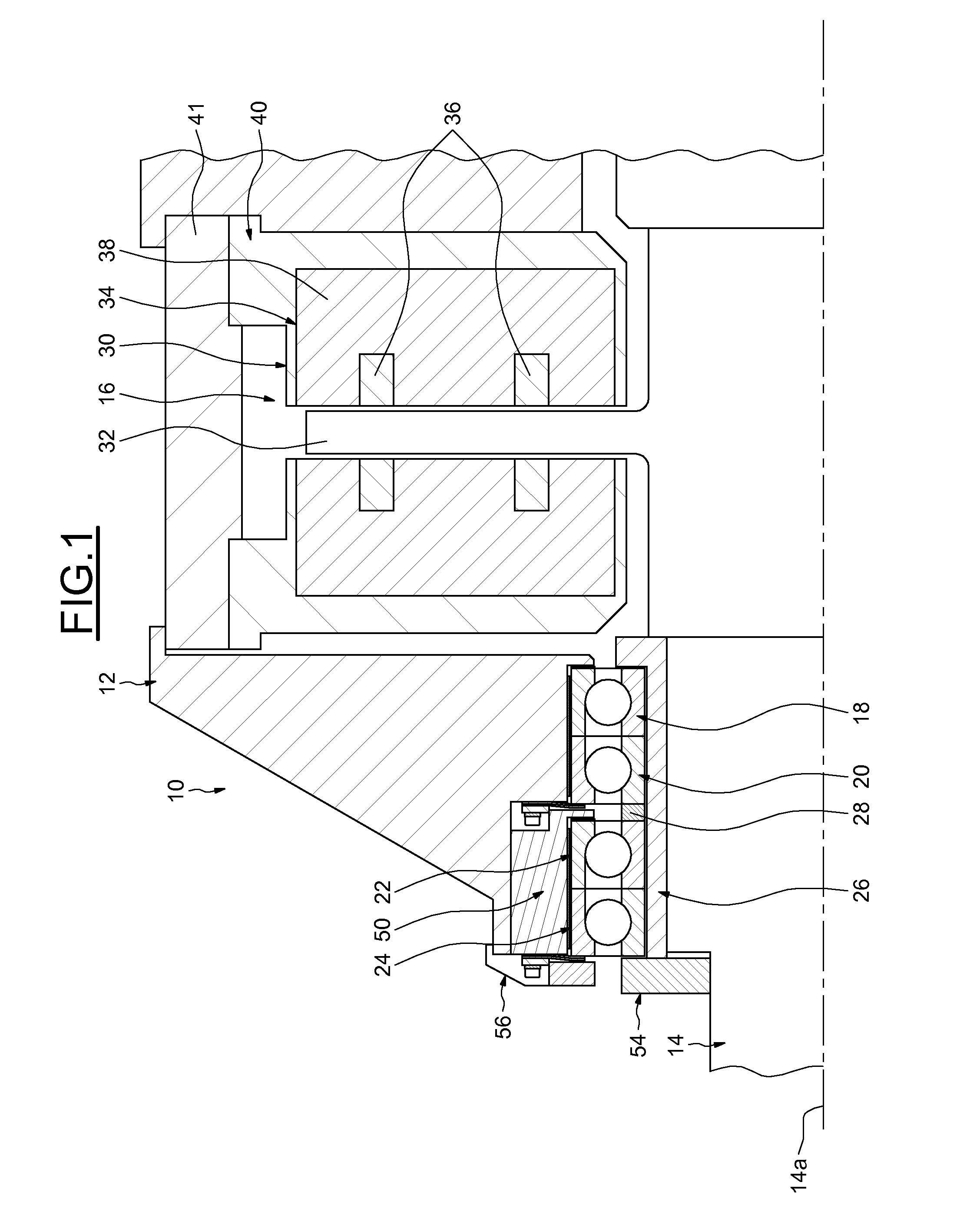
[0025]FIG. 1 partially illustrates an embodiment of a rotating machine 10 of the invention. The rotating machine 10 comprises a casing 12, a rotating shaft 14 extending along an axis 14a and adapted to support a rotor part (not shown). For example, if the rotating machine is a centrifugal compressor, the rotor part comprises impellers. The rotating shaft and the associated rotor part form a rotor assembly.

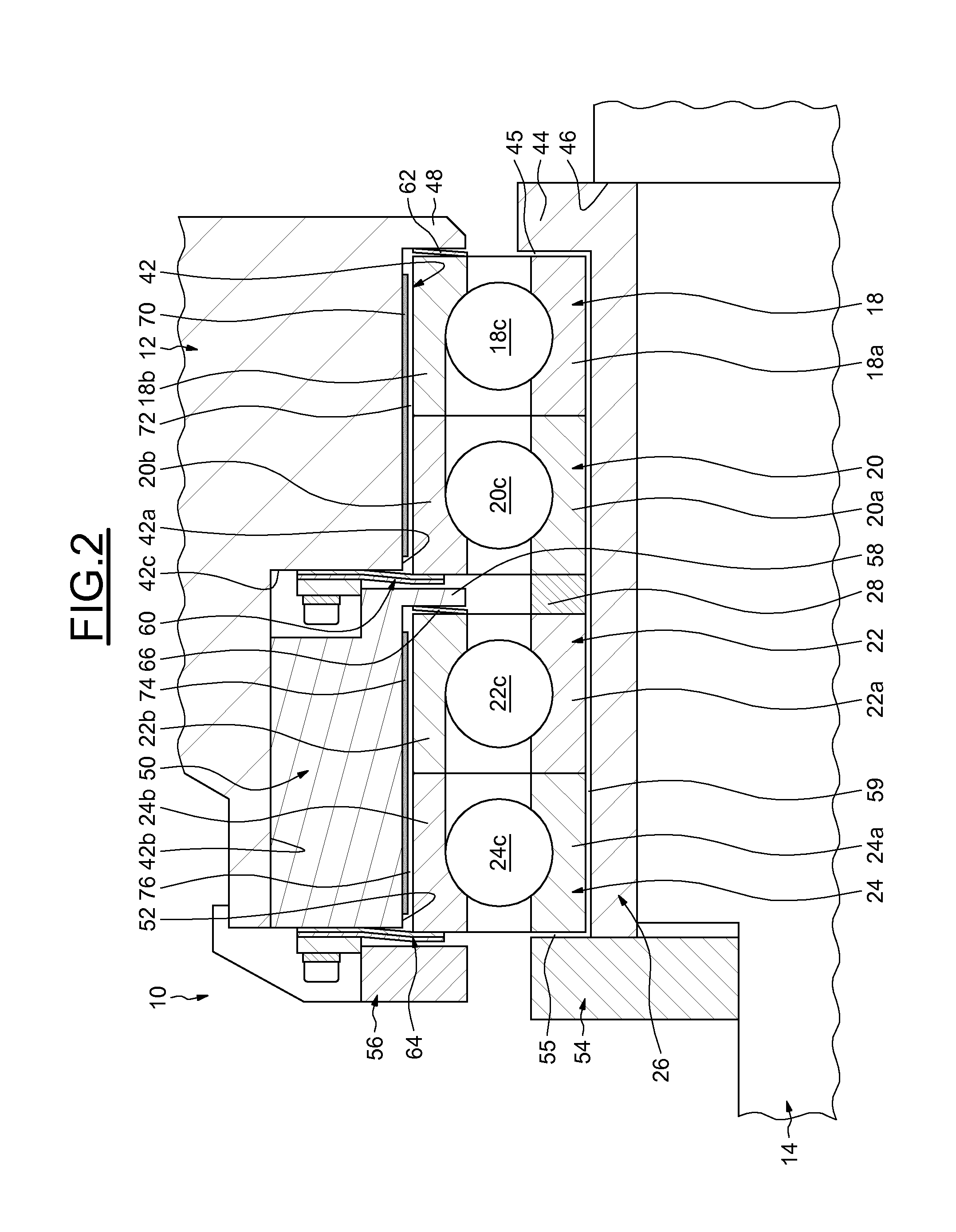
[0026]The rotating machine 10 also comprises at least one main active magnetic bearing 16 connected to the shaft 14 and supporting the shaft inside the casing 12, and auxiliary rolling bearings 18 to 24 associated to the magnetic bearing 16 and radially mounted between the shaft 14 and the casing 12 to support and transmit radial and axial loads therebetween when the magnetic bearing 16 is not operating normally....


PUM


Abstract

A rotating machine comprises a shaft, a casing, at least one main magnetic bearing connected to the shaft for rotatably supporting said shaft inside the casing, at least one first and one second auxiliary rolling bearings positioned between the shaft and the casing to support axial and radial loads, and first and second axial abutment means positioned on the shaft to transmit axial loads to inner rings of the rolling bearings. The machine further comprises a spacer axially positioned between facing faces of the inner rings of said rolling bearings for the transmission of the axial loads between said inner rings, and at least a first axial retaining means positioned on the casing and located axially between facing faces of the outer rings for the transmission of the axial loads between at least one of said outer rings and the casing.

Description

BACKGROUND[0001]The embodiments disclosed relate generally to rotating machines with at least a main active magnetic bearing and auxiliary rolling bearings. In particular, the embodiments relate to rotating turbomachines such as compressors, expanders, turbines, pumps, etc. The turbomachines are used in engines, turbines, power generation, cryogenic applications, oil and gas, petrochemical applications, etc.[0002]One turbomachine often used in the industry includes a centrifugal compressor which increases the pressure of a compressible gas through the use of mechanical energy by rotating centrifugal impellers through which the gas passes. The impellers are attached to a compressor shaft. The rotating shaft and the associated impellers form a rotor assembly which is supported in the stator of the compressor by active radial and axial magnetic bearings.[0003]The active magnetic bearings levitate and maintain the rotor assembly in position inside the stator by applying electromagnetic ...

Claims


Application Information

Patent Timeline
IPC IPC(8): F16C32/04F16C25/08F16C19/18F16C35/06F16C35/077
CPCF16C32/0442F16C35/061F16C25/083F16C19/183F16C35/077F04D29/058F04D29/059F16C27/04F16C39/02F16C19/163F16C2360/44F16C19/546F16C19/542F16C32/04F16C35/07F16C19/541
Inventor FALOMI, STEFANOBIGI, MANUELEFIORAVANTI, DUCCIOMEI, LUCIANO
Owner NUOVO PIGNONE TECH SRL
Why Eureka
Try Eureka