
Force Detection for Microscopy Based on Direct Tip Trajectory Observation

Active Publication Date: 2016-05-05
UNIVERSITY OF MISSOURI
View PDF0 Cites 2 Cited by
  • Summary
  • Abstract
  • Description
  • Claims
  • Application Information

AI Technical Summary

Benefits of technology

The invention is a scanning probe microscope that can directly observe and compute the force between the tapping tip and the object under observation, in real-space and in multiple dimensions. This new capability allows for more accurate and precise measurement of interaction force components, which improves the accuracy of microscope images and enables real-space monitoring of conformational dynamics of atoms, molecules, or larger scale objects and devices. The scanning probe microscope can also be an AFM, which allows for more natural and soft state observations of lipid or protein molecules without the need for solidification. Overall, this patent presents a significant improvement in the field of force microscopy and opens the door to new possibilities in research and technology development.

Problems solved by technology

It is challenging to infer 3D tip trajectories from this reduced coordinate system, even if the geometry of the tip and its orientation relative to the sample are known.
Furthermore, frictional coupling between the tip and sample causes complex dynamics, such as cantilever bowing and tip slipping that are convolved with the ΔZ signal.
This process can take hours to complete which limits the types of samples that can be studied as well as the experimental conditions.
However, as explained above and below, it is believed that these assumptions lead to inaccuracies with regard such indirect determinations of tip position.

Method used


Image

  • Force Detection for Microscopy Based on Direct Tip Trajectory Observation
  • Force Detection for Microscopy Based on Direct Tip Trajectory Observation
  • Force Detection for Microscopy Based on Direct Tip Trajectory Observation

Examples


Embodiment Construction

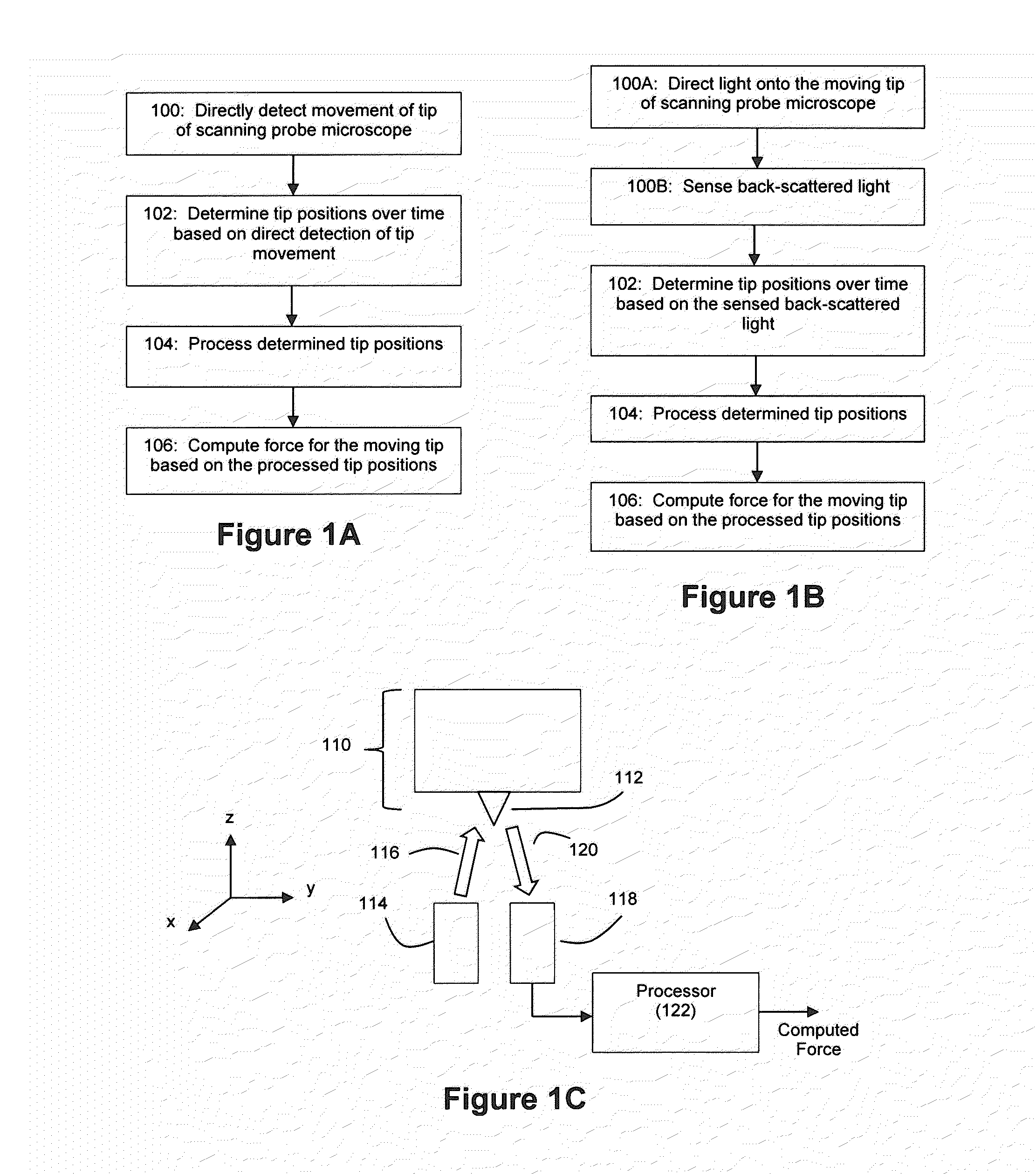
[0027]FIG. 1A depicts an example method for an example embodiment whereby tip movement for a scanning probe microscope is directly detected to support the computation of a force for the moving tip. The scanning probe microscope can be any microscope having a probe tip capable of movement, an example of which is an AFM. For example, an AFM such as an ultrastable AFM can be used as microscope 110 (see FIG. 1C).

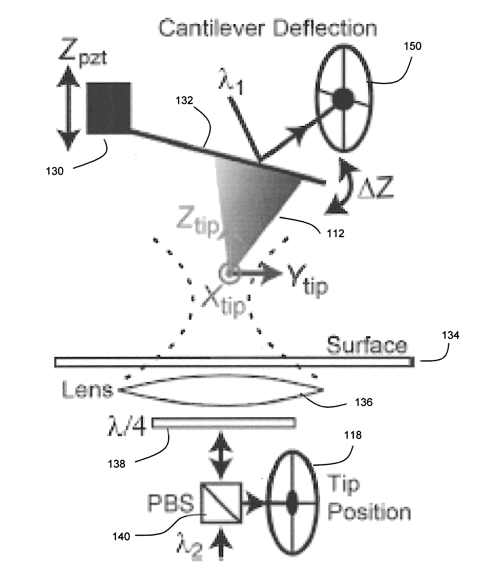
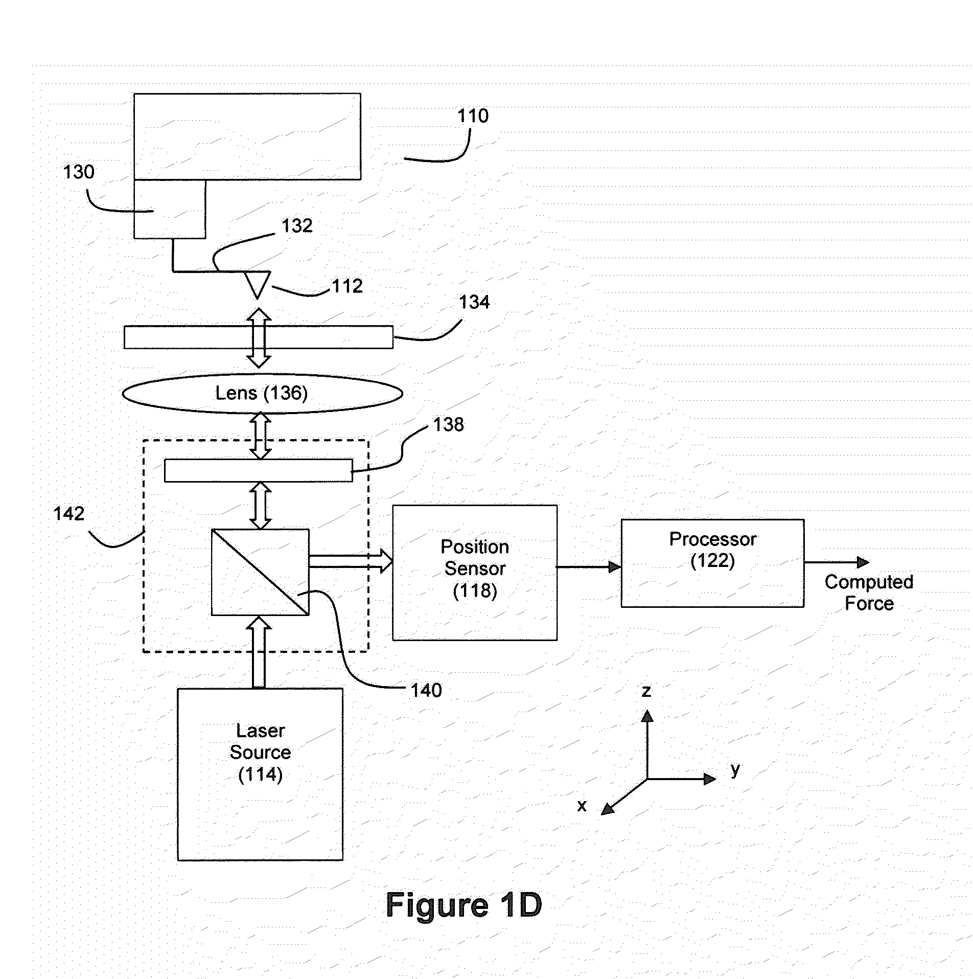
[0028]At step 100, the tip movement is directly detected by a position detector. Any of a number of techniques can be used for this direct detection of tip position. For example, the tip position can be optically detected and tracked, as described in connection with FIGS. 1B and 1C. FIG. 1B depicts an example method for an example embodiment where tip movement is optically detected, and FIG. 1C depicts an example embodiment of an apparatus capable of performing the method shown by FIG. 1B. As another example, the tip position can be directly detected via capacitance, where a cha...


PUM


Abstract

With example embodiments described herein, a probe tip of a scanning probe microscope (such as an atomic force microscope (AFM)) is directly detected as it moves in a tapping mode to determine the tip positions over time, and a force for the tip is computed from these determined tip positions.

Description

CROSS-REFERENCE AND PRIORITY CLAIM TO RELATED PATENT APPLICATION[0001]This patent application claims priority to U.S. provisional patent application Ser. No. 62 / 060,274, entitled “Force Detection for Microscopy Based on Direct Tip Trajectory Observation”, filed Oct. 6, 2014, the entire disclosure of which is incorporated herein by reference.STATEMENT REGARDING FEDERALLY SPONSORED RESEARCH OR DEVELOPMENT[0002]This invention was made with government support under CAREER Award #1054832 awarded by the National Science Foundation. The government has certain rights in the invention.INTRODUCTION[0003]The atomic force microscope (AFM) is a ubiquitous tool across nanoscience. AFM technique owes its popularity to its combination of high resolution coupled with high versatility—an AFM can operate well in vacuum and in liquid environments, and it can also operate well on conducting and insulating specimens such as biological molecules. A conventional AFM includes sharp tip affixed to the end of...

Claims


Application Information

Patent Timeline
IPC IPC(8): G01Q20/02G01Q60/24G01Q20/00
CPCG01Q20/02G01Q60/24G01Q20/00G01Q30/04G01Q60/34
Inventor KING, GAVIN MCLEANSIGDEL, KRISHNA PRASAD
Owner UNIVERSITY OF MISSOURI
Learn More