

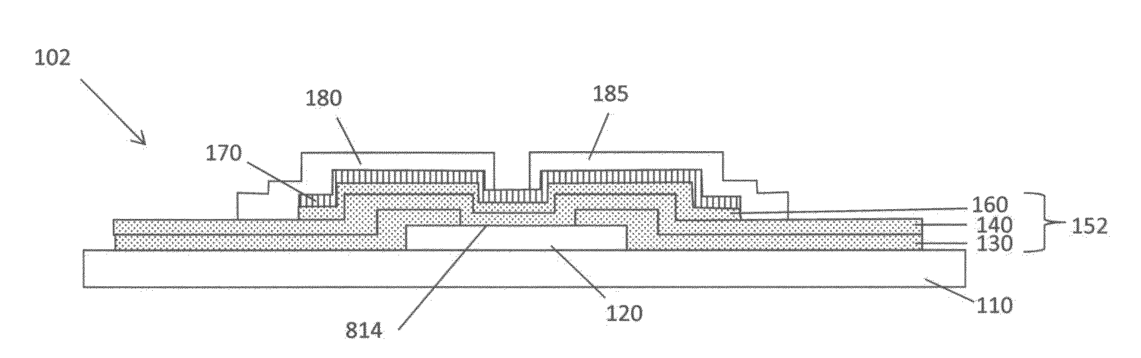
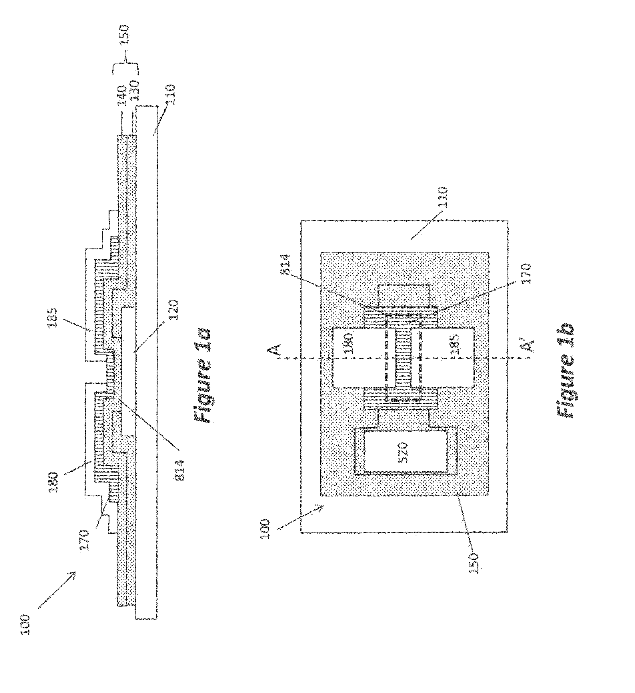
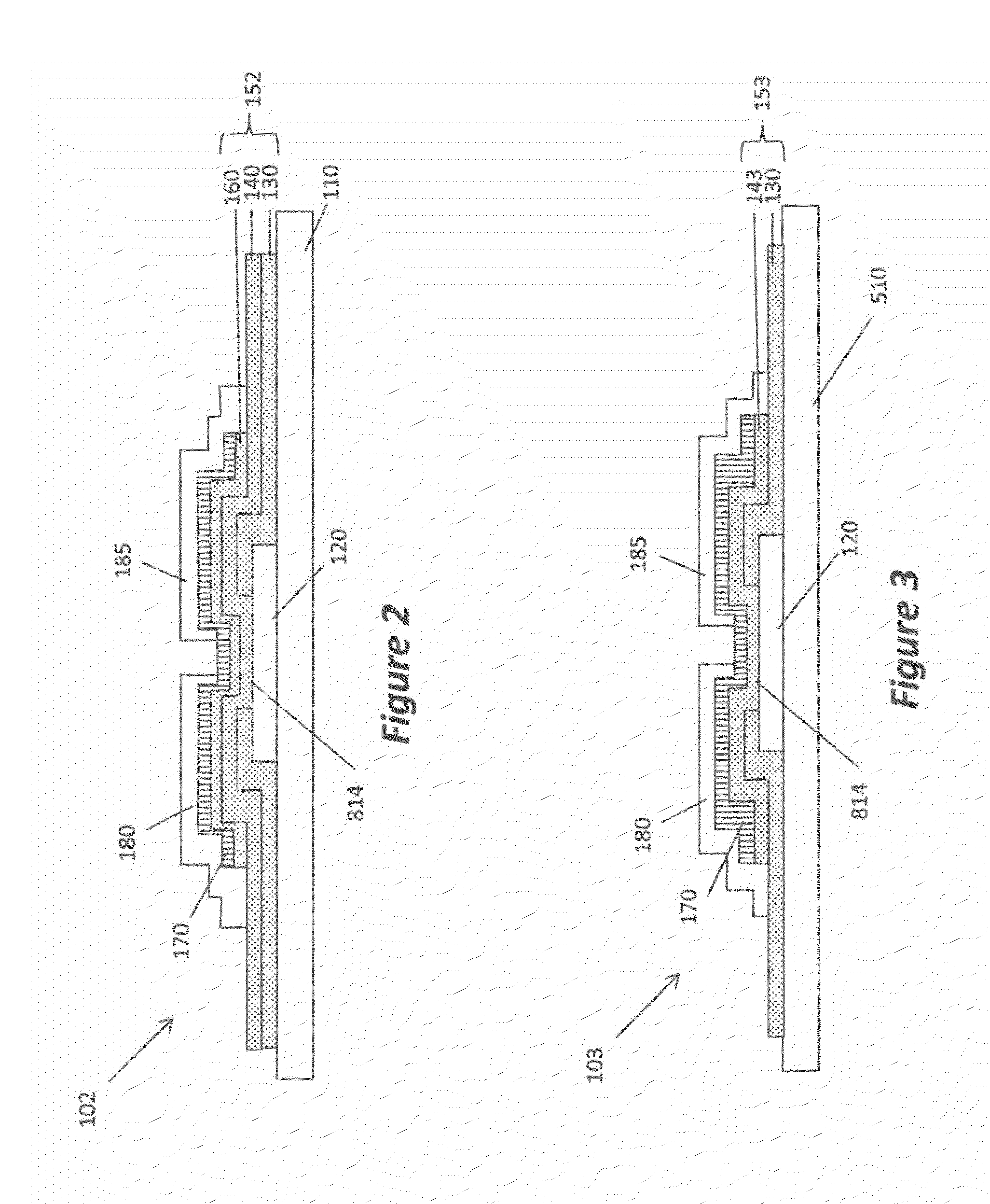
TFT substrate with variable dielectric thickness
a dielectric thickness and substrate technology, applied in the direction of semiconductors, semiconductor devices, electrical equipment, etc., can solve the problems of device processing, difficult to perform transistor component alignment across typical substrate widths up to one meter or more, and the impact of traditional photolithographic processes and equipmen
- Summary
- Abstract
- Description
- Claims
- Application Information
AI Technical Summary
Benefits of technology
Problems solved by technology
Method used
Image

Examples
examples
General Conditions for the Preparation of Layers Using Atmospheric Pressure ALD
[0129]The preparation of a thin film coating of the material layers on glass substrates as used in the examples is described below. The ALD coating device used to prepare these layers, namely aluminum oxide, ZnO:N, and Al-doped ZnO (AZO), has been described in detail in US Patent Application Publication No. US 2009 / 0130858, the disclosure of which is herein incorporated by reference in its entirety. The coating device has an output face (facing up) that contains spatially separated elongated gas channels and operates on a gas bearing principle. The coating device can be understood with respect to delivery head 900 shown in FIG. 28. Each gas channel is composed of an output slot 95, 93, 92 which supplies gas to the output face 905, and adjacent exhaust slots 91 which remove gas from the output face 905. The order of the gas channels is P-O-P-M-P-O-P-M-P-O-P where P represents a purge channel, O represents ...
example i1
Inventive Example I1
Bottom Gate TFT with an Extra 500 Å Outside of the Channel Region
[0136]Inventive Example I1 is a bottom-gate transistor with the variable thickness dielectric stack of the present invention. Inventive Example I1 was fabricated as Comparative Example C1 with the following exceptions. After removing the PVP used to pattern the gate, a 500 Å extra dielectric layer having a gate via was formed using selective area deposition. The transistors were completed and characterized as in comparative example C1. The performance data for Inventive Example I2 can be found in the Id-Vg curve shown in FIG. 29.
[0137]As can be seen in FIG. 29, the inventive examples having the extra dielectric outside of the channel region perform similarly to the comparative example without the extra dielectric layer, having the same gate dielectric thickness within the channel region.
All-Enhancement-Mode Inverters
[0138]In order to further probe the usefulness of the variable thickness dielectric ...
example i6
Inventive Example I6
Enhancement-Depletion-Mode Inverter with Common Dielectric Stack
[0146]Inventive Example I6 was fabricated using the combination of spatial ALD and selective area deposition (SAD) on a glass substrate. A 200 Å ZnO:N semiconductor layer for the top gate load TFT was formed first, so that the back channel was in contact with the glass. Next, the first conductive layer containing the gate of the bottom gate drive TFT and the source and drain for the load TFT was formed using 1000 Å AZO. A 400 Å common dielectric layer was formed from two separately patterned 200 Å dielectric layers of Al2O3 to make the gate dielectric for the load TFT and a portion of the gate dielectric for the drive TFT. Next, a buffer layer and the semiconductor layer of the drive TFT were formed from a single inhibitor pattern with 100 Å of Al2O3 and 200 Å of ZnO:N. The second conductive layer containing the source and drain of the bottom gate drive TFT and the gate for the load TFT was formed us...
PUM
 Abstract
Description
Claims
Application Information