Seal structure for wire harness

a technology of sealing structure and wire harness, which is applied in the direction of insulated conductors, cables, conductors, etc., can solve the problems of rust in the pipe, burden on the axial direction, and the inability to insert conductive wires constituting the wire, so as to achieve easy and smooth sealing and not compromise the effect of ability

Active Publication Date: 2016-05-05
SUMITOMO WIRING SYST LTD
View PDF3 Cites 19 Cited by
  • Summary
  • Abstract
  • Description
  • Claims
  • Application Information

AI Technical Summary

Benefits of technology

[0006]The present invention was made based on circumstances such as those described above, and it is an object thereof to provide a seal structure for a wire harness that can maintain the sealing ability with respect to a shield pipe and that can facilitate the operation of inserting conductive wires into a seal member.
[0008]According to the present invention, even if the protective member is damaged, and water enters the inside of the flexible shield member, the entry of water to the inside of the shield pipe is prevented by the seal member. Moreover, the conductive wire can be introduced into the wire insertion hole along the wire insertion path, that is, from the radial direction with respect to the wire insertion hole. Accordingly, this operation can be performed easily and smoothly when compared with an operation of inserting the conductive wire into the wire insertion hole from the axial direction. Also, even though this wire insertion path is formed, the sealing ability is not compromised because in a state in which the seal member is fitted in the shield pipe, the wire insertion path is kept watertight with at least an end surface thereof on the protective member side being closed.

Problems solved by technology

However, with respect to the above-described structure, there is a concern that if the corrugated tube is damaged, and a break or the like occurs therein, water entering the inside of the corrugated tube from this break or the like may reach the inside of the shield pipe and cause rust in the pipe.
However, even when such a rubber stopper is provided in the shield pipe, the operation of inserting the conductive wires constituting the wire harness into the wire insertion holes in the axial direction is burdensome and is by no means preferable in terms of working efficiency.

Method used


Image

  • Seal structure for wire harness
  • Seal structure for wire harness
  • Seal structure for wire harness

Examples


embodiment 1

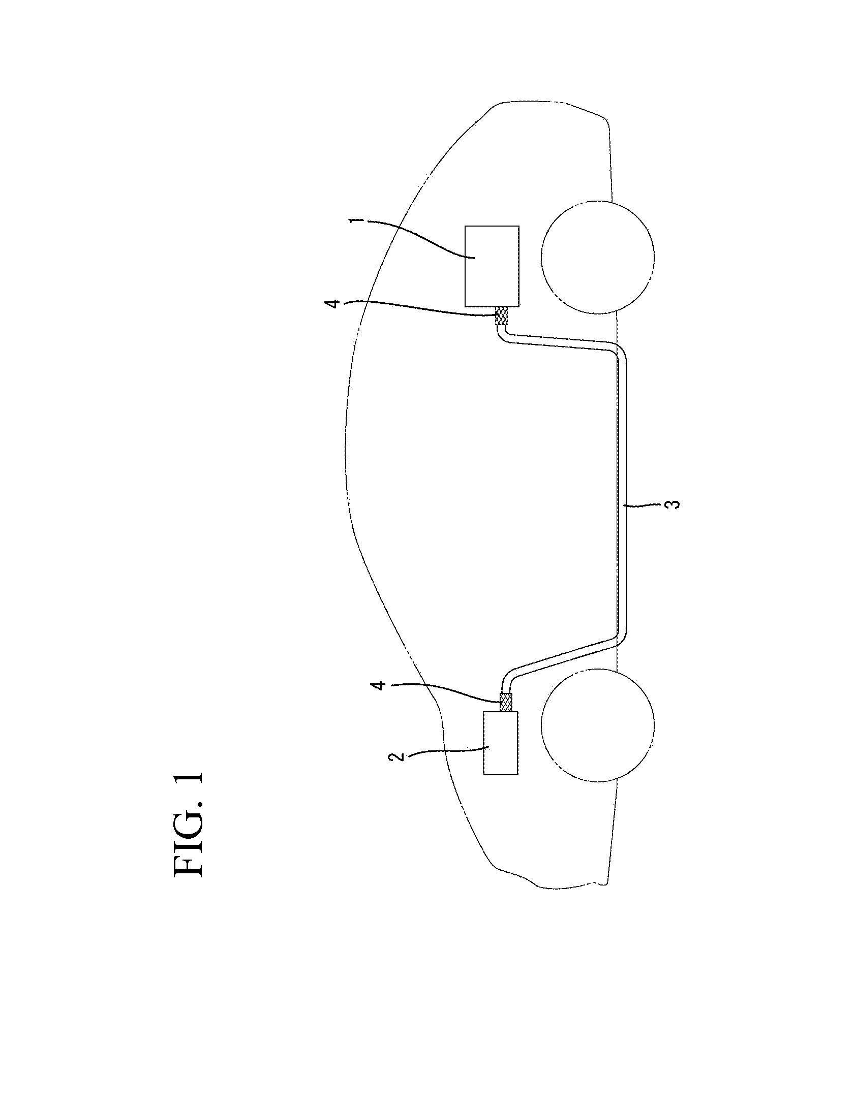
[0022]A seal structure for a wire harness of Embodiment 1 is applied to a hybrid vehicle.

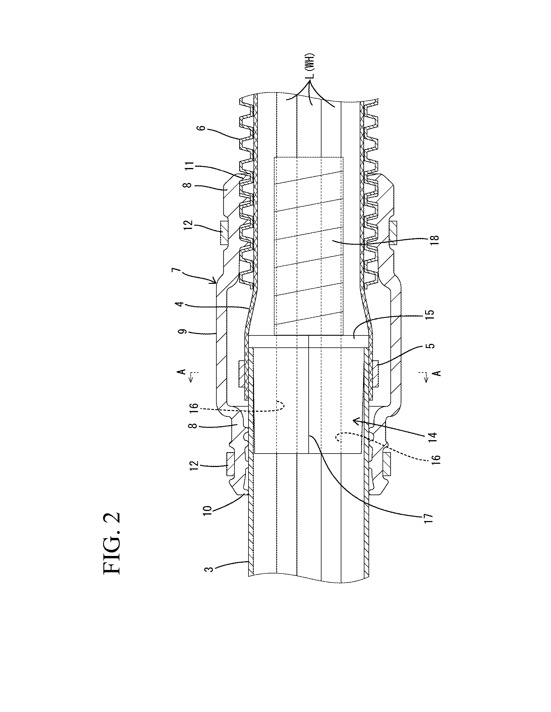
[0023]A wire harness WH connects a battery 1 that is installed on a rear side of the vehicle and an inverter 2 that is provided in an engine compartment to each other. In the case of the present embodiment, as shown in FIG. 2, the wire harness WH is constituted by three flexible conductive wires L.

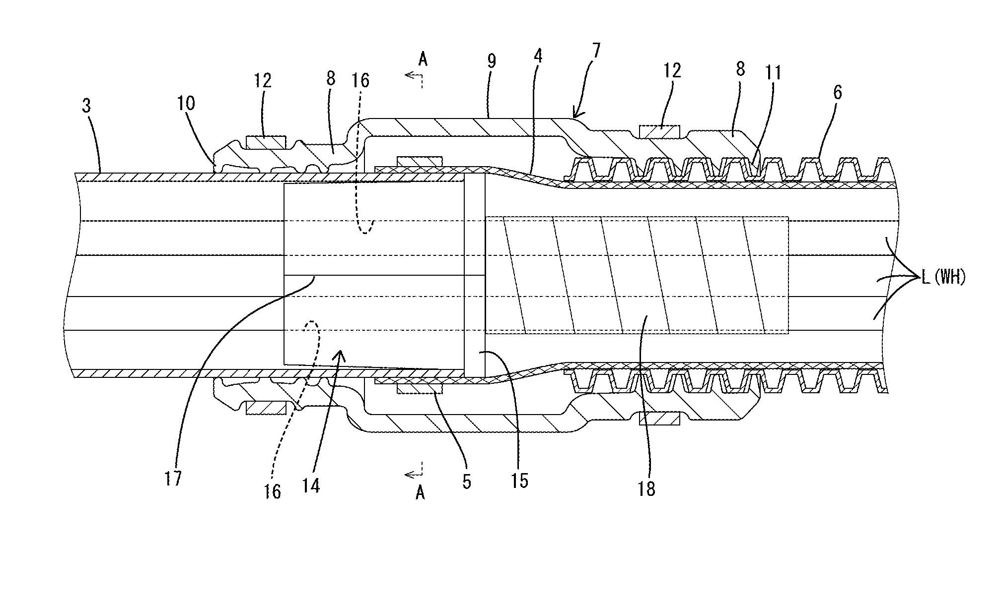
[0024]An intermediate portion of the wire harness WH is collectively inserted in a shield pipe 3 that is disposed in an under-floor area of the vehicle. The shield pipe 3 is made of aluminum or an aluminum alloy and is composed of an elongated pipe having a circular cross-sectional shape. The shield pipe 3 is bent to be routed along a predetermined pipe arrangement route. The shield pipe 3 generally extends horizontally in a substantially front-rear direction of the vehicle. A front end side of the shield pipe 3 is bent upward to be introduced into the engine compartment, and a rear end side thereof is...

embodiment 2

[0040]FIG. 5 shows a seal member 14A according to Embodiment 2 of the present invention. In Embodiment 1, the wire insertion paths 17 of the seal members 14 are in the form of straight line-shaped cuts that are made along the axial direction, whereas wire insertion paths 17A of Embodiment 2 are in the form of wavy line-shaped cuts that are made along the axial direction to reach the corresponding wire insertion holes 16.

[0041]The thus formed seal members 14A allow the path length of the wire insertion paths 17A from an end surface on the leading end side to an end surface on the inward side, of each seal member 14A, to be increased and also allow the contact area between opposing surfaces of each wire insertion path 17A to be increased even more. Therefore, the entry of water to the inside of the shield pipe 3 can be more reliably prevented.

[0042]The other components are the same as those of Embodiment 1, and thus the same effects can be provided.

embodiment 3

[0043]FIG. 6 shows a seal member 14B according to Embodiment 3 of the present invention. In Embodiment 2, the wire insertion paths 17A in the form of wavy line-shaped cuts that are each composed of curved lines over the entire path in the axial direction are described. However, wire insertion paths 17B of Embodiment 3 are formed into the form of wavy line-shaped cuts that are each composed of straight lines over the entire path in the axial direction.

[0044]The thus configured Embodiment 3 also can provide the same effects as Embodiment 2.


PUM


Abstract

Sealing ability with respect to a shield pipe is ensured. A wire harness is inserted in the inside of a shield pipe and a braid portion, and furthermore, a corrugated tube is disposed on the outer side of the braid portion. A sealing grommet is disposed to extend across a connecting portion between the shield pipe and the braid portion. A seal member made of rubber is pushed into an end portion of the shield pipe. A wire insertion hole in which a conductive wire of the wire harness is inserted penetrates the seal member, and a wire insertion path is formed in an outer circumferential surface of the seal member toward the wire insertion hole. Thus, the conductive wire can be inserted into the wire insertion hole from a radial direction.

Description

TECHNICAL FIELD[0001]The present invention relates to a seal structure for a wire harness.BACKGROUND ART[0002]Conventionally, in hybrid vehicles or electric automobiles, there are cases where a wire harness constituted by a plurality of wires is routed between a battery and an inverter in a state in which the wire harness is inserted in a metal shield pipe. An example of such a wire harness is disclosed in JP 2006-311699A.[0003]In the case of the aforementioned wire harness, the shield pipe is routed along an under-floor area of a vehicle. On the other hand, in a portion of the wires that is led out of the shield pipe, that is, in a region where the wires are routed toward the battery or the inverter, the wires are inserted in a flexible metal braid portion and are able to be routed freely. Moreover, conventionally, the metal braid portion is inserted in a corrugated tube for the purpose of waterproofing and the like, and furthermore, the shield pipe and the corrugated tube are conn...

Claims


Application Information

Patent Timeline
Patent Type & Authority Applications(United States)
IPC IPC(8): H02G3/04B60R16/02
CPCH02G3/0462H02G3/0406B60R16/0222H01B7/17H01B7/18H01B7/285H02G3/22H05K7/00B60R16/0215H02G3/0691Y02A30/14
Inventor MAEDA, TAKAMASA
Owner SUMITOMO WIRING SYST LTD
Why Eureka
Try Eureka