Wireless Energy Transfer Using Alignment Of Electromagnetic Waves

a technology of electromagnetic waves and wires, applied in the direction of transformers/inductances, antennas, inductances, etc., can solve the problems of limited tethered solutions to powering portable devices, corresponding increase in energy consumption of these devices, and physical limitations of how much energy a portable device can stor

Active Publication Date: 2016-05-05
TESLONIX
View PDF38 Cites 32 Cited by
  • Summary
  • Abstract
  • Description
  • Claims
  • Application Information

AI Technical Summary

Benefits of technology

[0011]Alternative embodiments of the method for wireless communication include one of the following features, or any combination thereof. Receiving, at a power access point, from at least one of the energizable devices a telemetry data, the power access point capable of at least one of tracking of one of the device responses, the forming of one of the plurality of energy beams and the aligning of the phase of each of the EM waves for an at least two of the energy beams. Aligning a respective polarity of the one or more EM waves for the at least one of the energy beams to another polarity of the another EM wave of the another one of the energy beams. The at least one energy beam is directed to more than one of the energizable devices on a time-shared basis. The at least one energy beam is directed to a new energizable device in response to a relocation of one of the plurality of energizable devices.

Problems solved by technology

Increased processing and connectivity capabilities of portable devices have resulted in a corresponding increase in the energy consumption of these devices.
Furthermore, there are practical physical limits as to how much energy a portable device can store, thus necessitating frequent charging of these devices.
Tethered solutions to powering portable devices are limited in part due to a lack of standardization of the connectors between the power cable and device, the weight and reliability of the charging cables, restrictions on the operating environment (e.g. underwater or hazardous areas), and the general constraints on mobility that tethered solutions impose.
Wireless charging of portable devices, has previously been limited to short distances (e.g. on the order of centimeters) by near-field techniques such as inductive or capacitive coupling.
Far-field techniques that use lasers or microwave beams involve dangerously high power levels, particularly in an environment including humans.
Lasers and microwave beams are also typically limited to line-of-sight applications.
However, previous solutions have been limited in their ability to efficiently power devices in an IoT environment, where the devices require mobility, and have significantly different power consumption requirements.

Method used


Image

  • Wireless Energy Transfer Using Alignment Of Electromagnetic Waves
  • Wireless Energy Transfer Using Alignment Of Electromagnetic Waves
  • Wireless Energy Transfer Using Alignment Of Electromagnetic Waves

Examples


embodiment 10

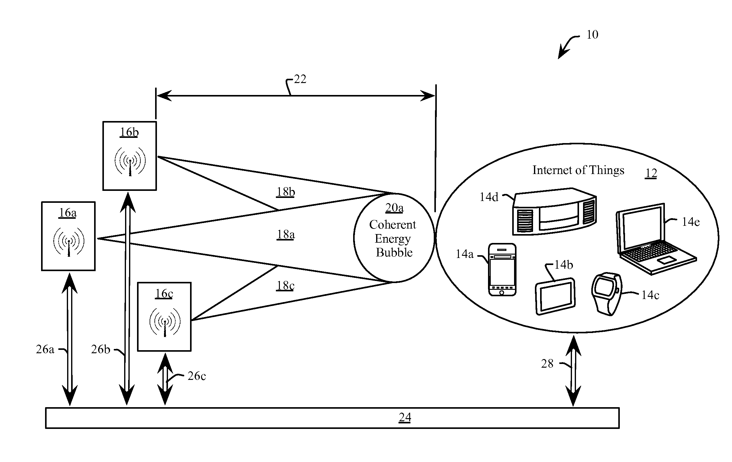
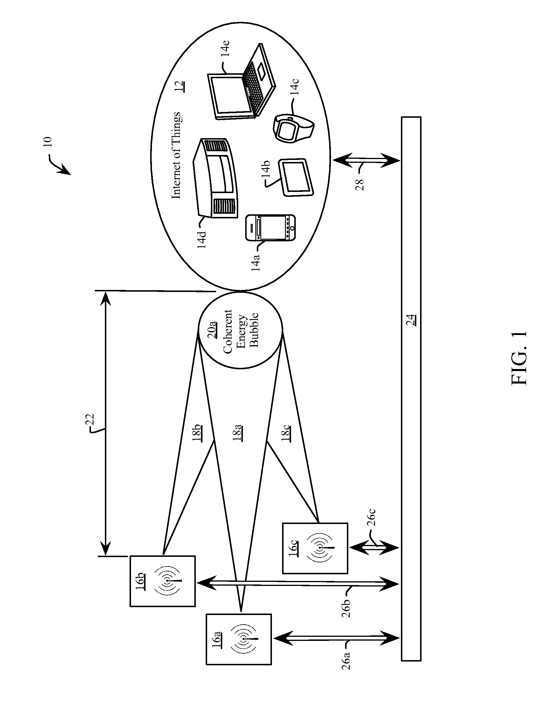
[0028]Referring to FIG. 1 an embodiment 10 of a system for wireless energy transfer provides energy (e.g. “powers”) an IoT 12, including for example a cell phone 14a, a tablet 14b, a smart watch 14c, a stereo 14d and a computer 14e. The energizable devices 14a through 14e (generally 14) are merely illustrative and should not be considered to constrain the potential devices that would comprise the IoT 12. In one example, all of the devices 14 are of the same type. In another example, the devices 14 are low power devices such as RFID tags. In another example, the devices 14 are high power devices, such as motorized wheelchairs. Various embodiments replace the IoT 12 with one or more devices 14 that need not be associated with, nor communicate, with one another.

[0029]The devices 14 of the IoT 12 receive energy from a plurality of power access points 16a, 16b and 16c (generally 16). Each power access point 16a, 16b and 16c emits a respective energy beam 18a, 18b and 18c (generally 18), ...

embodiment 30

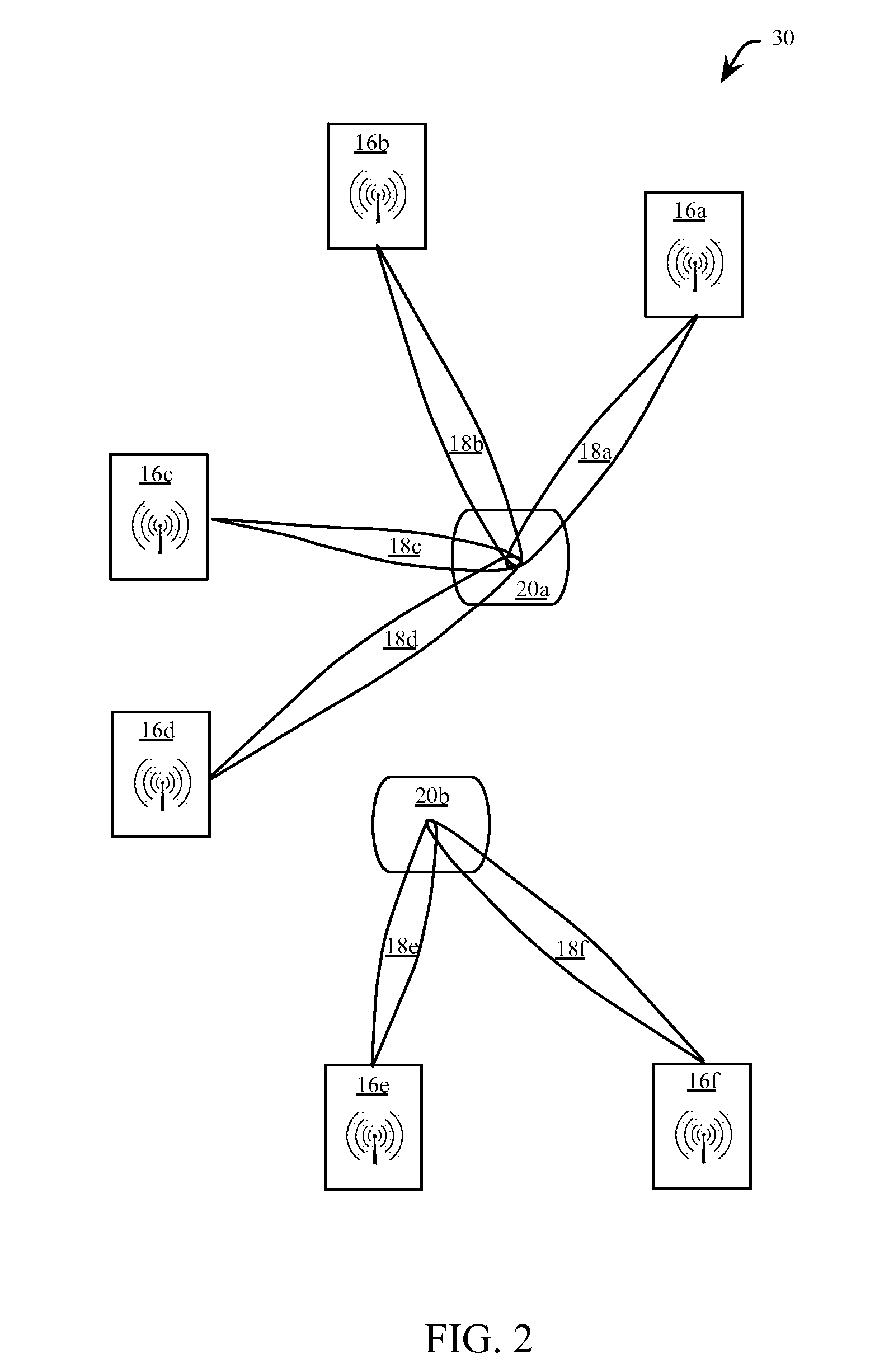
[0043]FIG. 2, FIG. 3 and FIG. 4 show three embodiments wherein energy beams 18 are reconfigured to form coherent energy bubbles that track the changing positions of a plurality of devices. With reference to FIG. 1 and FIG. 2, the embodiment 30 of FIG. 2 includes the three power access points 16a, 16b and 16c of FIG.1, transmitting respective energy beams 18a, 18b and 18c to form a coherent energy bubble 20a. A fourth power access point 16d transmits a energy beam 18d towards the coherent energy bubble 20a. As with the foregoing description of FIG. 1, the energy bubble 20a is coincident with a receiving antenna of an energizable device. The energy of each energy beam 18a, 18b, 18c and 18d is lower than the energy for each of the same beams 18a, 18b and 18c in FIG. 1 for the same required total energy received at the coherent energy bubble 20a. In one embodiment, the energy of at least one of the energy beams 18a, 18b, 18c and 18d is different from each other energy beam, wherein the ...

embodiment 80

[0072]When the WIL section 84 is operating as a master, the frequency scaler 122 decreases the fundamental frequency from the oscillator 92 to provide a reference clock frequency to the WIL antenna that does not interfere with the frequency for the energy beam. In the embodiment 80 the oscillator 92 provides a fundamental frequency, which is scaled by 0.5 to create a 2.9 GHz reference clock frequency. Prior to all of the power access points being frequency locked, the spectrum near to the fundamental frequency will be noisy, hence it is desirable to frequency scale the fundamental frequency from the oscillator 92 to generate a reliable reference clock frequency for frequency locking with other power access points. In other embodiments, the oscillator 92 operates at a frequency appropriate for WIL (e.g. 2.9 GHz) and the energy beam section 82 scales the oscillator frequency to generate an appropriate frequency for the energy beam (e.g. 5.8 GHz).

[0073]Continuing the example embodiment...


PUM


Abstract

A method for wireless energy transfer includes forming a plurality of energy beams. Each energy beam includes one or more electromagnetic (EM) waves having a same fundamental frequency as another EM wave of another one of the energy beams. A device response of an energizable device to the plurality of energy beams incident thereon is tracked. The one or more EM waves for each of the plurality of energy beams is directed to power the energizable device. A respective phase of the one or more EM waves for at least one of the energy beams is aligned to another phase of another EM wave of another one of the energy beams. A received power level received by the energizable device is maximized according to the device response by optimizing for at least one of the energy beams, the directing, and the aligning of the phase, of the one or more EM waves.

Description

CROSS-REFERENCE TO RELATED APPLICATIONS[0001]This application is a utility application claiming priority to co-pending U.S. Provisional Application Ser. No. 62 / 073,448 filed on Oct. 31, 2014 entitled “DISTANCE WIRELESS CHARGING USING CHARGING STATIONS,” co-pending U.S. Provisional Application Ser. No. 62 / 085,450 filed on Nov. 28, 2014 entitled “WIRELESS POWER TRANSFER AS APPLIED TO SOLAR PANELS,” co-pending U.S. Provisional Application Ser. No. 62 / 129,325 filed on Mar. 6, 2015 entitled “WIRELESS POWER TRANSFER USING ELECTROMAGNETIC WAVES ALIGNMENT,” and co-pending U.S. Provisional Application Ser. No. 62 / 136,142 filed on Mar. 20, 2015 entitled “WIRELESS POWER TRANSMISSION,” the entireties of which are incorporated by reference herein.FIELD[0002]This disclosure relates generally to wireless energy transfer, and more specifically to efficient systems and methods for the wireless transfer of energy using alignment of electromagnetic waves.BACKGROUND[0003]Increased processing and connec...

Claims


Application Information

Patent Timeline
Patent Type & Authority Applications(United States)
IPC IPC(8): H02J5/00H01Q3/00
CPCH01Q3/00H02J5/005H02J50/20H02J50/90H02J50/40
Inventor WIGHT, JAMES STUARTAMAYA, RONY EVERILDOSLABY, CEZARY PAUL
Owner TESLONIX
Why Eureka
Try Eureka