Video encoding device, video encoding method, and program-containing non-transitory computer-readable medium

a video encoding and video encoding technology, applied in the field of video processing technology, can solve the problems of deteriorating the image quality of the latter macroblock, reducing the output quality of the generated code, and reducing the subjective image quality, so as to achieve high quality

Inactive Publication Date: 2016-05-05
NEC CORP
View PDF2 Cites 0 Cited by
  • Summary
  • Abstract
  • Description
  • Claims
  • Application Information

AI Technical Summary

Benefits of technology

This technology helps to make high-quality videos when controlling the amount of data used to store them. This means that the video is encoded in a way that makes the resulting file have a specific size.

Problems solved by technology

This means that a larger quantization step leads to rougher quantization and consequently makes the generated code size small.
This consequently deteriorates the image quality of the latter macroblocks.
In addition, due to the variation in quantization step between the macroblocks, areas for which rough quantization is performed stand out, which deteriorates subjective image quality.
This consequently deteriorates image quality of the latter pictures.
In addition, due to the variation in quantization step between the pictures, pictures for which rough quantization is performed stand out, which deteriorates subjective image quality.
For this reason, when generated code size is larger than estimated code size, code size to be allocated to the subsequent areas (macroblocks or pictures) is reduced, consequently deteriorating the image quality of the subsequent areas.
This reduces the effect of adaptive quantization, consequently deteriorating image quality.
Accordingly, when the target picture and the past picture have a low correlation, for example, when the pattern of the target picture is significantly different from that of the past picture, or when a scene is changed to a different scene, the generated code size for the target picture is estimated significantly wrong, and distribution of the code size becomes inaccurate, which consequently causes a problem that encoding efficiency is deteriorated.

Method used


Image

  • Video encoding device, video encoding method, and program-containing non-transitory computer-readable medium
  • Video encoding device, video encoding method, and program-containing non-transitory computer-readable medium
  • Video encoding device, video encoding method, and program-containing non-transitory computer-readable medium

Examples


first exemplary embodiment

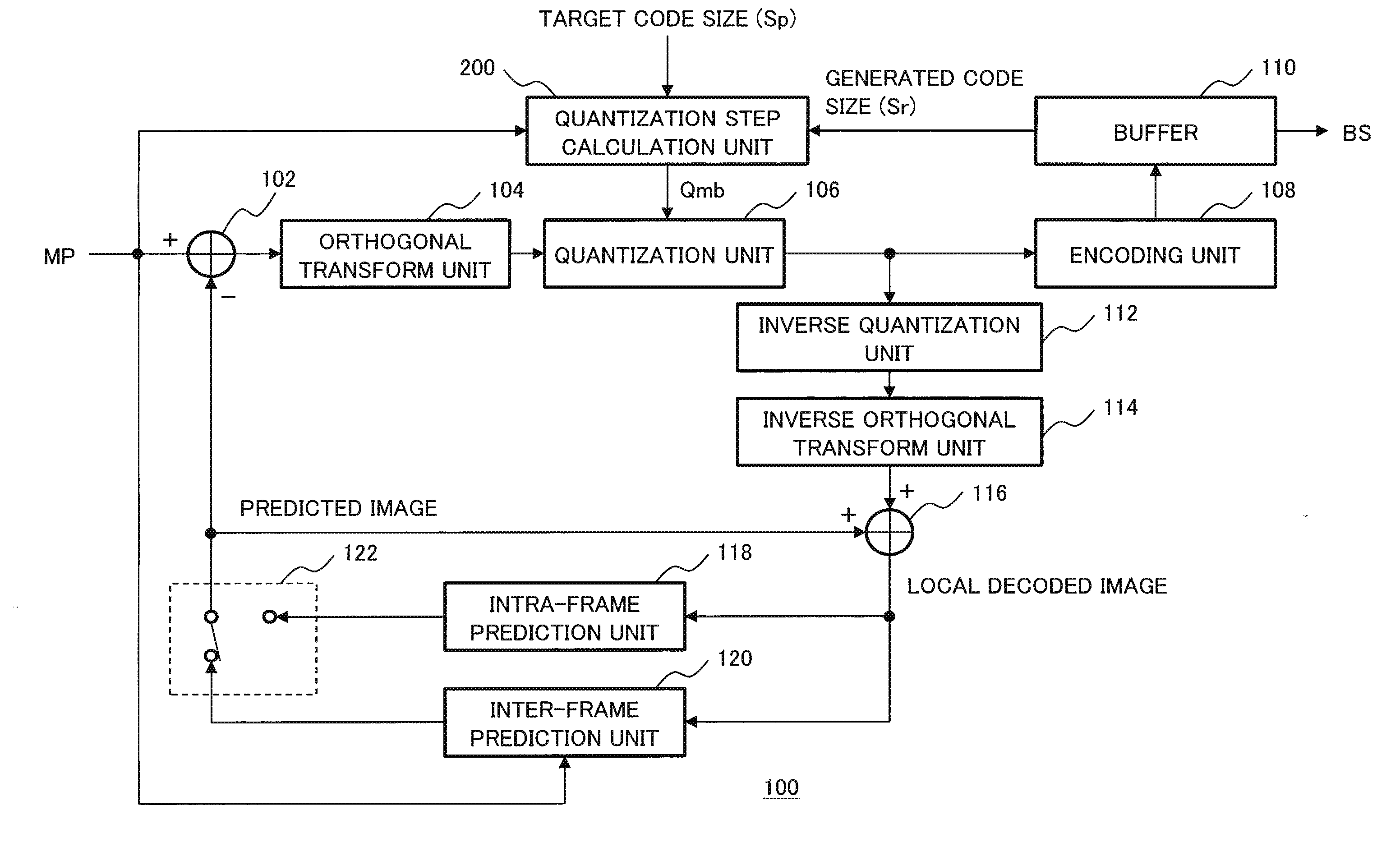
[0064]FIG. 1 illustrates a video encoding device 100 according to a first exemplary embodiment of the present invention. The video encoding device 100 encodes a video MP at a variable rate in accordance with, for example, an MPEG format to obtain a bitstream BS and output the bitstream, and includes an arithmetic unit 102, an orthogonal transform unit 104, a quantization unit 106, an encoding unit 108, a buffer 110, an inverse quantization unit 112, an inverse orthogonal transform unit 114, an arithmetic unit 116, an intra-frame prediction unit 118, an inter-frame prediction unit 120, a switch 122, and a quantization step calculation unit 200.

[0065]The data of the video MP is received by the arithmetic unit 102. The arithmetic unit 102 calculates, for each macroblock of the input video MP, a difference between the data and data of a predicted image of the macroblock input from the intra-frame prediction unit 118 or the inter-frame prediction unit 120 through the switch 122, and outp...

second exemplary embodiment

[0100]In the video encoding device 100 of the first exemplary embodiment described above, the complexity estimation unit 202 of the quantization step calculation unit 200 estimates, as the complexity Xest of the target picture, the product of the generated code size and the average quantization step of the encoded picture whose type is the same as that of the target picture in accordance with the technology of TM5. Then, the complexity estimation unit 202 calculates the complexity Xmb of each macroblock by dividing the estimated complexity Xest by the total number n of macroblocks.

[0101]The technology disclosed in PTL 3, for example, may be used for the estimation of the complexity of the target picture in the complexity estimation unit 202. Specifically, the complexity Xest for an I picture to be encoded first after a scene change is estimated on the basis of the variance value of the picture, and the complexity Xest for a picture that is a P picture or a B picture to be encoded fi...

third exemplary embodiment

[0105]In the first and second exemplary embodiments described above, the same complexity Xmb is calculated for each macroblock by estimating the complexity of the target picture and dividing the estimated complexity by the total number of the macroblocks, but the complexity Xmb may be calculated for each macroblock.

[0106]In this case, following Equation (10), for example, can be used for calculation of the complexity Xmb.

Xmb=a×(Fmb)2+b×Fmb+c   (10)

[0107]Equation (10) is obtained by replacing the feature quantity F of the entire target picture in Equation (5) with the feature quantity Fmb of the macroblock. The feature quantity F and the feature quantity Fmb are of the same type.

[0108]Needless to say, a fixed value determined in advance may also be used for each coefficient in Equation (10), and each coefficient may also be adjusted dynamically by the multiple regression analysis or the like.


PUM


Abstract

A video encoding device includes: circuitry configured to perform an orthogonal transform on a target picture to obtain an orthogonal transform coefficient; quantize the orthogonal transform coefficient for each macroblock of the target picture; and calculate, for a target macroblock in the target picture, a base quantization step which is a variable for matching a generated code size of the target picture with a target code size set for the target picture, determine a quantization step to be applied to quantizing for the target macroblock by weighting the calculated base quantization step with an activity of the target macroblock, and provide the quantization step.

Description

TECHNICAL FIELD[0001]The present invention relates to a video processing technology, and more specifically to a video encoding technology.BACKGROUND ART[0002]In image compression methods, represented by Moving Pictures Expert Group (MPEG) standards, including combination of motion compensation and discrete cosine transform (DCT), rate control is performed so that a bitstream is transmitted to a transmission line at a desired rate.[0003]FIG. 4 illustrates an MPEG layer structure. MPEG defines a layer structure including a sequence layer, a GOP (Group of Picture) layer, a picture layer, a slice layer, and a macroblock (MB) layer. The actual code size for a certain time period can be adjusted by changing a quantization step by adjusting data (Q scale) included in the slice layer and the MB layer. It is so designed that a larger Q scale sets a larger quantization step. In the following description, a quantization step is denoted by Q.[0004]FIG. 5 is a graph illustrating a relationship b...

Claims


Application Information

Patent Timeline
IPC IPC(8): H04N19/126H04N19/176H04N19/159H04N19/115H04N19/14
CPCH04N19/126H04N19/115H04N19/176H04N19/159H04N19/14
InventorTAKANO, FUMIYO
OwnerNEC CORP