Mold for forming a joint spacer device or a part thereof

a technology a mold, which is applied in the field of molds for forming a joint spacer device or a part thereof, can solve the problems of allergic reactions and several drawbacks of traditional molds, and achieve the effect of easy production at competitive costs

Active Publication Date: 2016-05-12
COSSINGTON LTD
View PDF5 Cites 11 Cited by
  • Summary
  • Abstract
  • Description
  • Claims
  • Application Information

AI Technical Summary

Benefits of technology

[0008]Therefore, it is the main object of the present invention to improve the state of the art in the industry sector of molds for the forming of joint spacer devices or a part thereof.
[0011]It is a further object of the present invention to provide a mold for the forming of a joint spacer device or a part thereof, which does not require laborious finishing steps of the spacer extracted thereof.
[0012]It is still another object of the present invention to provide a mold for the forming of a joint spacer device or a part thereof, which is easy to make at competitive costs.

Problems solved by technology

The traditional molds suffer from several drawbacks.
In the first place, being these made in elastically yielding-deformable material, such as silicone, they do not allow obtaining a spacer device with a definite shape in optimal manner, for which reason, once extracted from the mold, a spacer device must be machined superficially and finished, in order to obtain the exact required shape.
It can cap happen, however, that such a washing does not remove completely from the mold the traces of the antibiotic or additive therapeutic substance with bone cement used for a previous spacer device, with the result that allergic reactions may occur in spacer devices made with an antibiotic to which a patient is not allergic, which was, however, made in a mold used previously with bone cement supplemented with an antibiotic to which the patient is allergic

Method used


Image

  • Mold for forming a joint spacer device or a part thereof
  • Mold for forming a joint spacer device or a part thereof
  • Mold for forming a joint spacer device or a part thereof

Examples


first embodiment

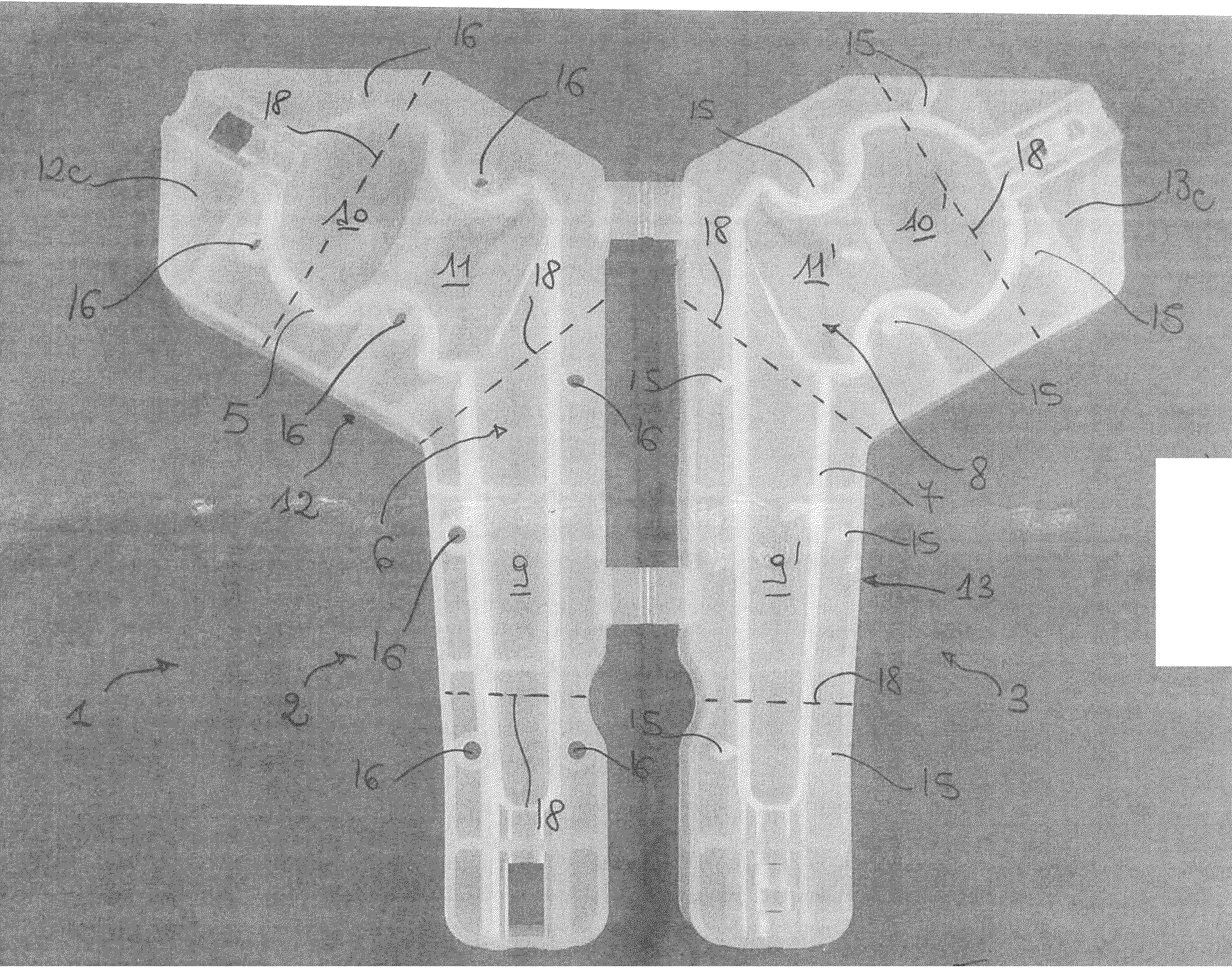
[0040]With particular reference to FIGS. 1 to 5, which illustrate a mold for forming a joint spacer device according to this invention, it will be noted that, in such a mold, the perimeter profile 5 of the rigid container body 2 circumscribes a forming surface for a longitudinal half of a joint spacer device for hip, and the perimeter profile 7 of the rigid cover 3 circumscribes a second molding surface 8 for the other longitudinal half of such a spacer device.

[0041]Each molding surface 6 and 8 comprises a stem portion 9, 9′, a head portion 10, 10′, and a connection portion 11, 11′ between the stem portion and the head portion.

[0042]In the mold according to the first embodiment of the present invention the perimeter profiles 5 and 7 coincide with the access opening to the container body 2 and the cover 3, respectively. across the access opening it is possible to cast the bone cement supplemented with a suitable antibiotic, pouring it on the first molding surface 6 and on the second ...

second embodiment

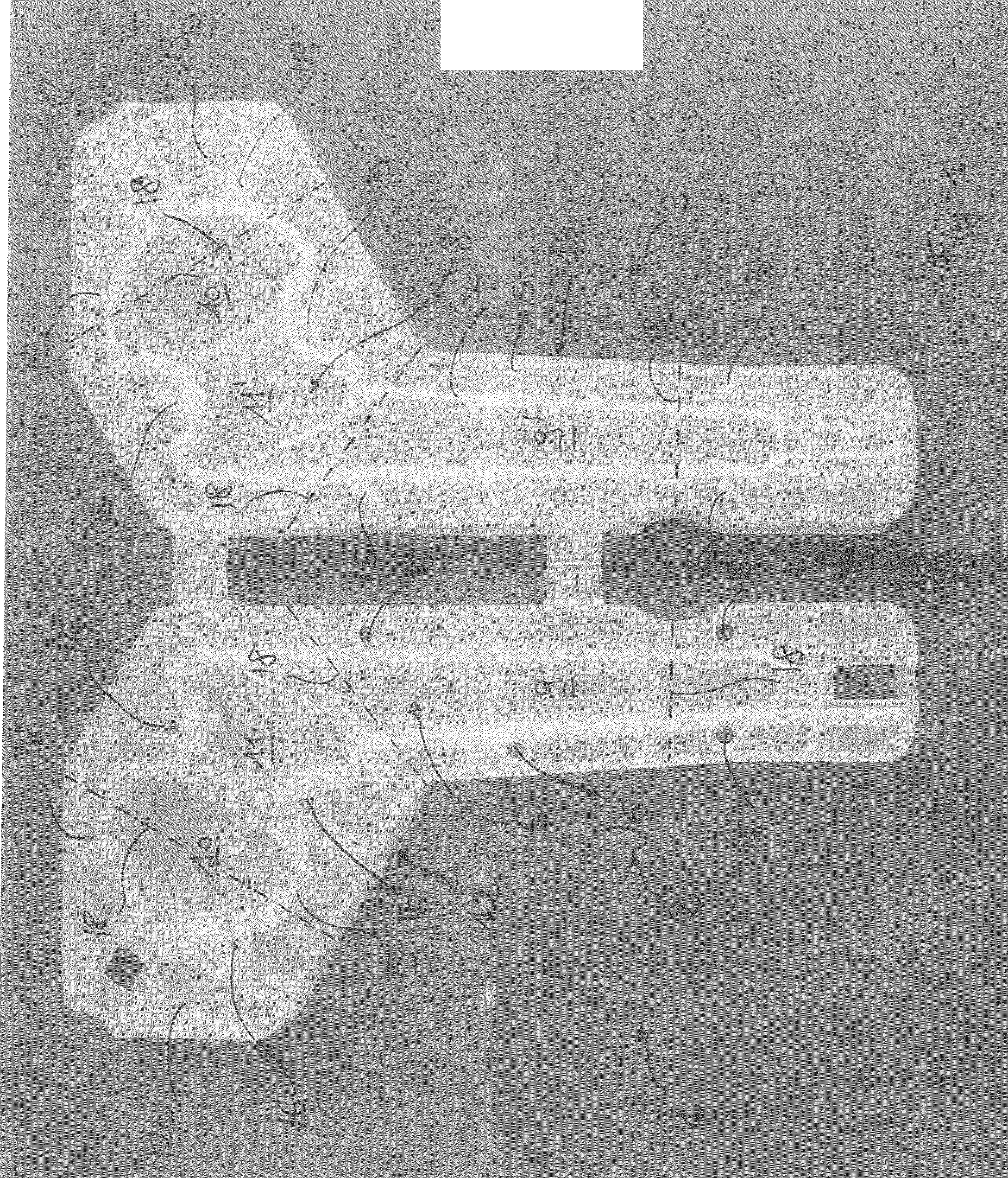
[0052]The mold 1 according to the present invention, see in particular the annexed FIGS. 6 to 10, is particularly suitable for forming a tibial portion of a spacer device for knee joint and comprises at least a rigid container body 2 and at least a rigid cover 3, which can be coupled with each other to delimit a cavity 4 corresponding to the external configuration of such component or tibial part.

[0053]More particularly, the rigid container body 2 of the mold according to the invention has a substantially “C”-shaped plan configuration and comprises a bottom wall 19 from which side walls 20 rise. The side walls 20 end at the top with an edge 21, at an upper access opening 22.

[0054]The rigid container body 2 is provided with at least a first perimeter profile 5, which upperly delimits at least a first molding surface 6 intended to shape at least a first part of the joint spacer device.

[0055]The first perimeter profile 5 is defined by an internal shoulder at the side walls 20, at a dis...

third embodiment

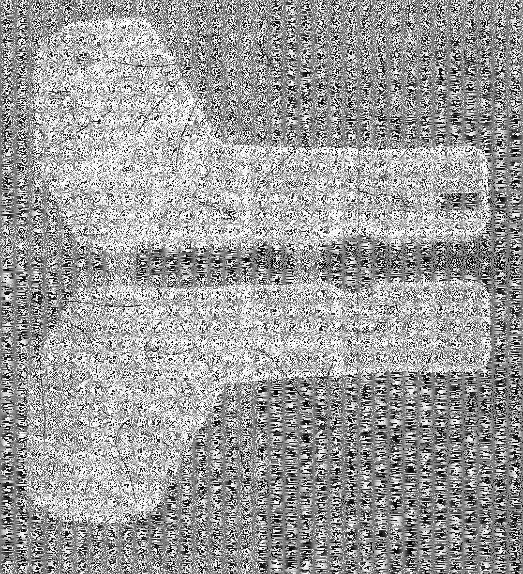
[0065]The annexed FIGS. 11 to 16 show the mold for the forming of a joint spacer according to the present invention, in particular suitable for forming a component or femoral part of a knee joint spacer device . Such a mold comprises at least a rigid container body 2 and at least a rigid cover 3, which can be coupled with each other to delimit a cavity 4 (FIG. 16) corresponding to the external configuration of such component or femoral part.

[0066]More particularly, the rigid container body 2 of the mold according to the invention has a substantially “C”-shaped plan configuration and circumscribes a bottom wall 19 from which side walls 20 rise. The side walls 20 end at the top with an edge 21 at an upper access opening 22.

[0067]The bottom wall 19 of the container body 2 of the mold 1 according to the third embodiment of this invention is substantially concave and has a central portion 19a and two end portions 19b and 19c, at the free ends of “C”. The central portion 19a is substantia...


PUM

PropertyMeasurementUnit
perimeteraaaaaaaaaa
shapeaaaaaaaaaa
thicknessaaaaaaaaaa

Abstract

A mold for forming a joint spacer device or a part thereof includes a rigid container body having a first perimeter profile delimiting a first molding surface configured to shape a first portion of the joint spacer or a part thereof; and a rigid cover provided with a second perimeter profile delimiting a second molding surface configured to shape a second portion of the joint spacer or a part thereof. The rigid container body and the rigid cover are removably engageable to each other, at the first and the second perimeter profile, so as to delimit a cavity corresponding to the external configuration of the joint spacer or the part thereof. The mold includes a weakening system on the rigid container body and on the rigid cover so that they are separable into parts to allow the extraction of a spacer device or a part thereof, molded therebetween.

Description

FIELD OF THE INVENTION[0001]This invention relates to a mold for forming a joint spacer device or a part thereof, and a spacer device obtained by means of such a mold.BACKGROUND OF THE INVENTION[0002]At the state of the art molds for joint spacer devices are known, which are usually made in elastically deformable material, such as, for example, silicone or other elastomeric suitable material, and intended to be filled with bone cement supplemented with antibiotic or other therapeutic substance, when the latter is in the fluid and malleable mass phase, for the purpose of obtaining a finished spacer device.[0003]The bone cement supplemented with antibiotic or other therapeutic substance, after having hardened in such a mold, is subsequently removed therefrom and the joint spacer thus obtained, once finished off, is implanted in the joint space of a patient to treat a disease in progress in the tissues surrounding such joint space.[0004]The traditional molds suffer from several drawbac...

Claims


Application Information

Patent Timeline
Patent Type & Authority Applications(United States)
IPC IPC(8): B29C33/44
CPCB29L2031/757B29C33/448A61F2/3859A61F2/3094A61F2/36A61F2/389A61F2002/30471A61F2002/30561A61F2002/30672A61F2002/30957A61F2310/00353
Inventor CAPPELLETTI, AVA
Owner COSSINGTON LTD
Why Eureka
Try Eureka