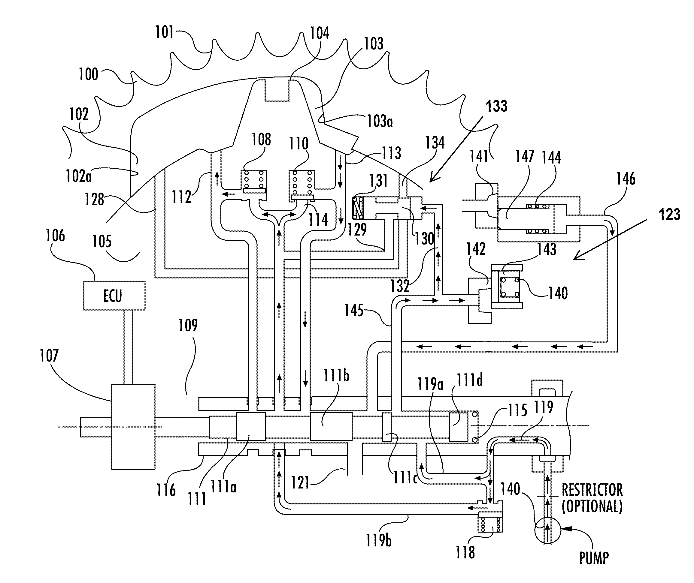
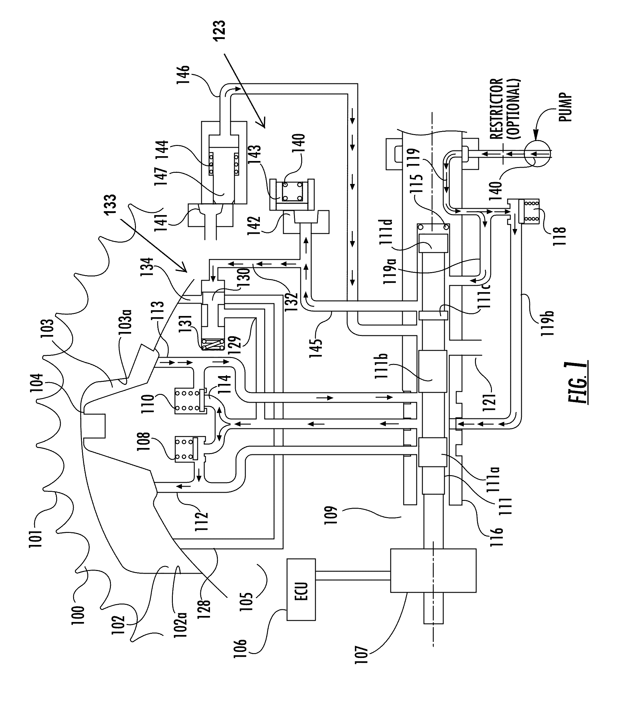
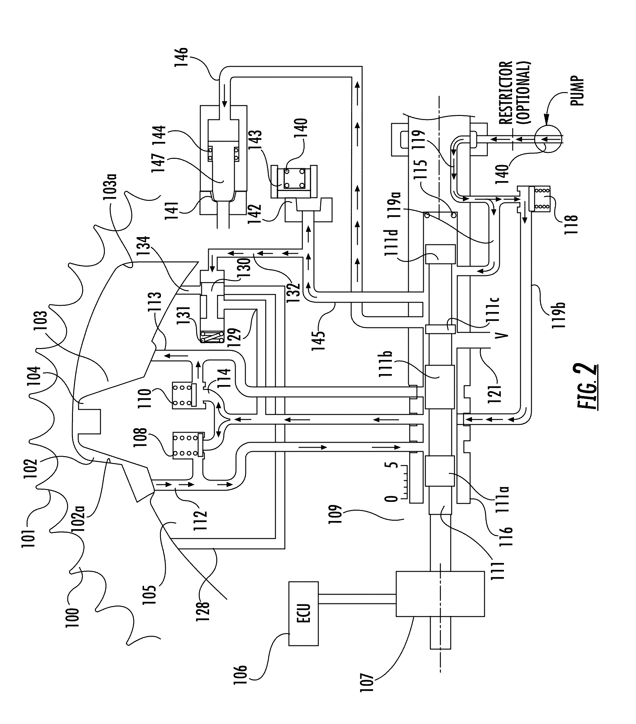
Variable camshaft timing mechanism with a lock pin engaged by oil pressure

Active Publication Date: 2016-05-12
BORG WARNER INC
View PDF1 Cites 10 Cited by
  • Summary
  • Abstract
  • Description
  • Claims
  • Application Information

AI Technical Summary

Benefits of technology

[0012]In an alternate embodiment, an accumulator may be in fluid communication with the lock pin s

Problems solved by technology

The problem with OPA or TA systems in executing the strategies discussed above is that the oil control valve defaults to a position that exhausts all the oil from either the advance or retard working chambers and fills the opposing chamber.
The OPA or TA systems are unable to direct the VCT phaser to any other position during the engine start cycle when the engine is not developing any oil pressure.
This limits the phaser to being able to move in one direction only in the engine shut down mode.

Method used


Image

  • Variable camshaft timing mechanism with a lock pin engaged by oil pressure
  • Variable camshaft timing mechanism with a lock pin engaged by oil pressure
  • Variable camshaft timing mechanism with a lock pin engaged by oil pressure

Examples


Example

[0097]FIG. 6 shows a phaser of a second embodiment in the retard locking position at the full retard position or retard end stop position. This phaser is similar to the phaser of FIG. 2, with an accumulator 200 added to line 146. Since it is anticipated that the oil behind the end lock pin 147 may leak out sooner than desired allowing the end lock pin 147 to disengage before the hot engine is restarted, an accumulator 200 may be in fluid communication with line 146 of the lock pin switching circuit 123. The accumulator 200 increases the time in which the end lock pin 147 is engaged with the recess 141 after engine shut down. The accumulator 200 is a pressure storage reservoir in which a non-compressible hydraulic fluid is held under pressure by an external source 201, 202. In this embodiment, the external source is a spring 201 biased piston 202. The external source can also be a spring, a raised weight, or a compressed gas. The other positions, for example the null mode (holding po...

Example

[0099]FIG. 7 shows a phaser of a third embodiment in the retard locking position at the full retard position or retard end stop position. This phaser is similar to the phaser of FIG. 6, with an accumulator 200 added to line 146. The difference between this phaser and the phaser of FIG. 6 is the placement of the inlet check valve 118. In the phaser of FIG. 7, fluid is supplied to the intermediate lock pin 143 and the end lock pin 147 from a source S and flows through the inlet check valve 118 as opposed to prior to the inlet check valve 118 as shown in FIGS. 1-5.

[0100]It should be noted that in FIG. 6, the accumulator 200 could also communicate with lines 119, 119a or 119b and produce similar results as when the accumulator is placed in line 146.

[0101]It should be noted that while the end stop lock mode in FIGS. 6-7 were described as locking the phaser in a full retard position, the full retard position may be replaced with a locking of the phaser in a full advance position. In this ...


PUM


Abstract

A hydraulically operated camshaft phasing mechanism has two lock pins. One of the lock pins engages at an intermediate position and an end lock pin engages near one of the stops at the end of the phaser range of authority. At least one of the locking pins, preferably the end lock pin, when the vane is at an end stop position, is engaged by oil pressure and spring loaded to release when the oil pressure side of the end lock pin is vented.

Description

BACKGROUND OF THE INVENTION[0001]1. Field of the Invention[0002]The invention pertains to the field of variable cam timing. More particularly, the invention pertains to a variable camshaft timing mechanism with at least one lock pin engaged by oil pressure.[0003]2. Description of Related Art[0004]Internal combustion engines have employed various mechanisms to vary the relative timing between the camshaft and the crankshaft for improved engine performance or reduced emissions. The majority of these variable camshaft timing (VCT) mechanisms use one or more “vane phasers” on the engine camshaft (or camshafts, in a multiple-camshaft engine). As shown in the figures, vane phasers have a rotor 105 with one or more vanes 104, mounted to the end of the camshaft, surrounded by a housing assembly 100 with the vane chambers into which the vanes fit. It is possible to have the vanes 104 mounted to the housing assembly 100, and the chambers in the rotor assembly 105, as well. The housing's outer...

Claims


Application Information

Patent Timeline
IPC IPC(8): F01L1/34F01L1/047F01L1/04
CPCF01L1/34F01L1/047F01L1/044F01L13/00F01L31/00F02D13/02F01L1/3442F01L2001/34423F01L2001/34446F01L2001/34459F01L2001/34463F01L2001/34466F01L1/34409F01L2001/34469
Inventor SMITH, FRANKLIN R.BROWN, DANIEL
Owner BORG WARNER INC
Why Eureka
Try Eureka