Phase difference film, polarization plate, and liquid crystal display device

a technology of phase difference film and polarization plate, which is applied in the direction of optics, polarising elements, instruments, etc., can solve the problems of deteriorating front contrast of commercially available phase difference film, and achieve the effect of increasing the front contrast of the liquid crystal display devi

Active Publication Date: 2016-05-12
FUJIFILM CORP
View PDF11 Cites 22 Cited by
  • Summary
  • Abstract
  • Description
  • Claims
  • Application Information

AI Technical Summary

Benefits of technology

[0009]In order to solve the problems described above, an object of the present invention is to provide a phase difference film which is able to increase front contrast of the liquid crystal display device. In addition, another object of the present invention is to provide a polarization plate and a liquid crystal display device using the phase difference film.
[0031]According to the present invention, it is possible to provide a phase difference film which is able to increase front contrast of a liquid crystal display device. In addition, it is possible to provide a polarization plate and a liquid crystal display device using the phase difference film.

Problems solved by technology

However, currently, it has been found that front contrast considerably deteriorates in a commercially available phase difference film having a thickness of approximately 100 μm.

Method used


Image

  • Phase difference film, polarization plate, and liquid crystal display device
  • Phase difference film, polarization plate, and liquid crystal display device
  • Phase difference film, polarization plate, and liquid crystal display device

Examples


examples

[0223]Hereinafter, the present invention will be more specifically described with reference to examples. Materials, used amounts, ratios, treatment contents, treatment sequences, and the like of the following examples are able to be suitably changed unless the changes cause deviance from the gist of the present invention. Accordingly, the range of the present invention will not be limited to the following specific examples.

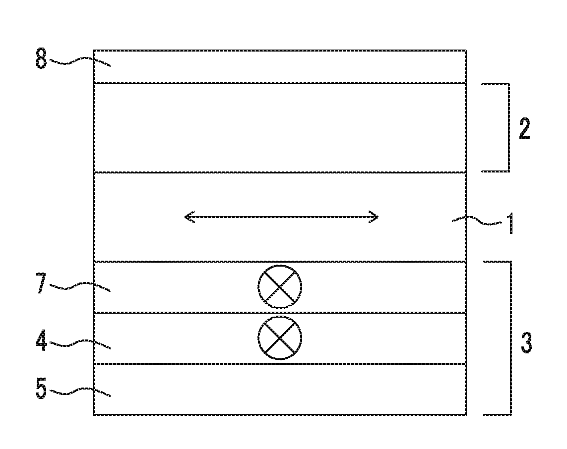
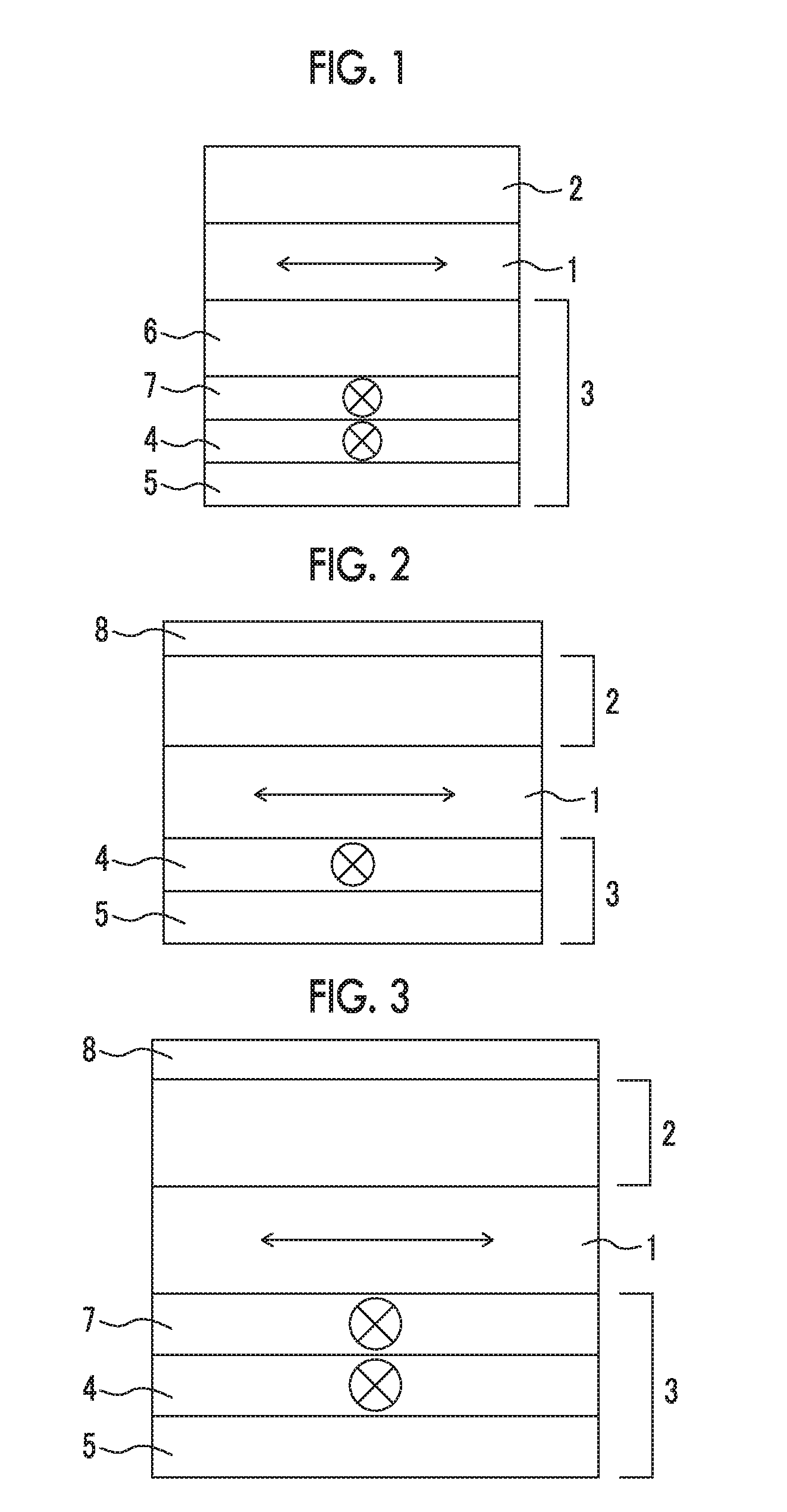
[0224](1) Preparation of Liquid Crystal Display Device of Layer Configuration a (Liquid Crystal Display Device Including Polarization Plate of FIG. 1)

[0225]

[0226]One surface of a cellulose film (manufactured by Fujifilm Corporation, zero retardation TAC, ZRF25, and thickness: 25 μm) was subjected to the following alkali saponification treatment.

[0227]The film (ZRF25) passed over a dielectric heating roll at a temperature of 60° C., the temperature of the film surface was heated to 40° C., and then an alkali solution (S-1) having the following composition was appli...


PUM

PropertyMeasurementUnit
thicknessaaaaaaaaaa
wavelengthaaaaaaaaaa

Abstract

A liquid crystal (LC) display device uses a phase difference film which increases front contrast of the device, and a polarization plate. The film includes a first optical anisotropic layer, and a second optical anisotropic layer thereon, the first layer formed by fixing an LC compound in a homogeneous alignment state, has an order parameter (OP) of 0.75 to 0.95, and layer thickness of 0.3 μm to 3.0 μm, the second layer formed by fixing an LC compound in a homeotropic alignment state, has an OP of 0.60 to 0.95, and layer thickness of 0.3 μm to 3.0 μm, the OP which is denoted by OP=(A∥−A⊥) / (2A⊥+A∥), “A∥” which represents absorbance of the LC compound regarding light polarized parallel to an alignment direction, and “A⊥” which represents absorbance of the LC compound to regarding light polarized vertical to the alignment direction.

Description

CROSS-REFERENCE TO RELATED APPLICATIONS[0001]This application is a Continuation of PCT International Application No. PCT / JP20141068858 filed on Jul. 16, 2014, which claims priority under 35 U.S.C. §119(a) to Japanese Patent Application No. 2013-149622 filed on Jul. 18, 2013 and Japanese Patent Application No. 2014-107922 filed on May 26, 2014. Each of the above application(s) is hereby expressly incorporated by reference, in its entirety, into the present application.BACKGROUND OF THE INVENTION[0002]1. Field of the Invention[0003]The present invention relates to a phase difference film. In addition, the present invention relates to a polarization plate and a liquid crystal display device using the phase difference film.[0004]2. Description of the Related Art[0005]Recently, a tablet or a mobile phone using a liquid crystal display device in an In-Place-Switching (IPS) mode has been widely used. For example, it has been considered that an optical anisotropic layer using alignment of a...

Claims


Application Information

Patent Timeline
Patent Type & Authority Applications(United States)
IPC IPC(8): G02B5/30G02F1/1337G02F1/1343G02F1/13363
CPCG02B5/3016G02F1/13363G02F2001/133742G02F1/134363G02F1/1337G02F1/133634G02F1/133633G02F1/133738G02F1/133742
Inventor TAKEDA, JUNKATOH, SHUNYANAGAI, MICHIOITO, YOJISUZUKI, MASAYA
Owner FUJIFILM CORP
Why Eureka
Try Eureka