
High-Resolution Scanning Microscopy

Active Publication Date: 2016-05-12
CARL ZEISS MICROSCOPY GMBH
View PDF16 Cites 12 Cited by
  • Summary
  • Abstract
  • Description
  • Claims
  • Application Information

AI Technical Summary

Benefits of technology

The invention is a method and apparatus for detecting a single image using a detector array that is larger than the image. The detector array can have a different size and arrangement than the image, and its pixels can be larger than the image's pixels. The method allows for the use of a larger detector array without needing to consider the limitations of the image's size. The detector array can be a detector row, which makes it easier to select the desired detector elements. The method also allows for the detection of changes in the fluorescence of the image over time, which can be useful for tracking applications. The invention also allows for modifications to the illumination distribution in scanning processes.

Problems solved by technology

Rather, it should also encompass situations in which the configuration fails to reach theoretical maximum by an error of 20%, due to actual insufficiencies or limitations.
The pixels of the detector array can additionally be too large for the required resolution.

Method used


Image

  • High-Resolution Scanning Microscopy
  • High-Resolution Scanning Microscopy
  • High-Resolution Scanning Microscopy

Examples


Embodiment Construction

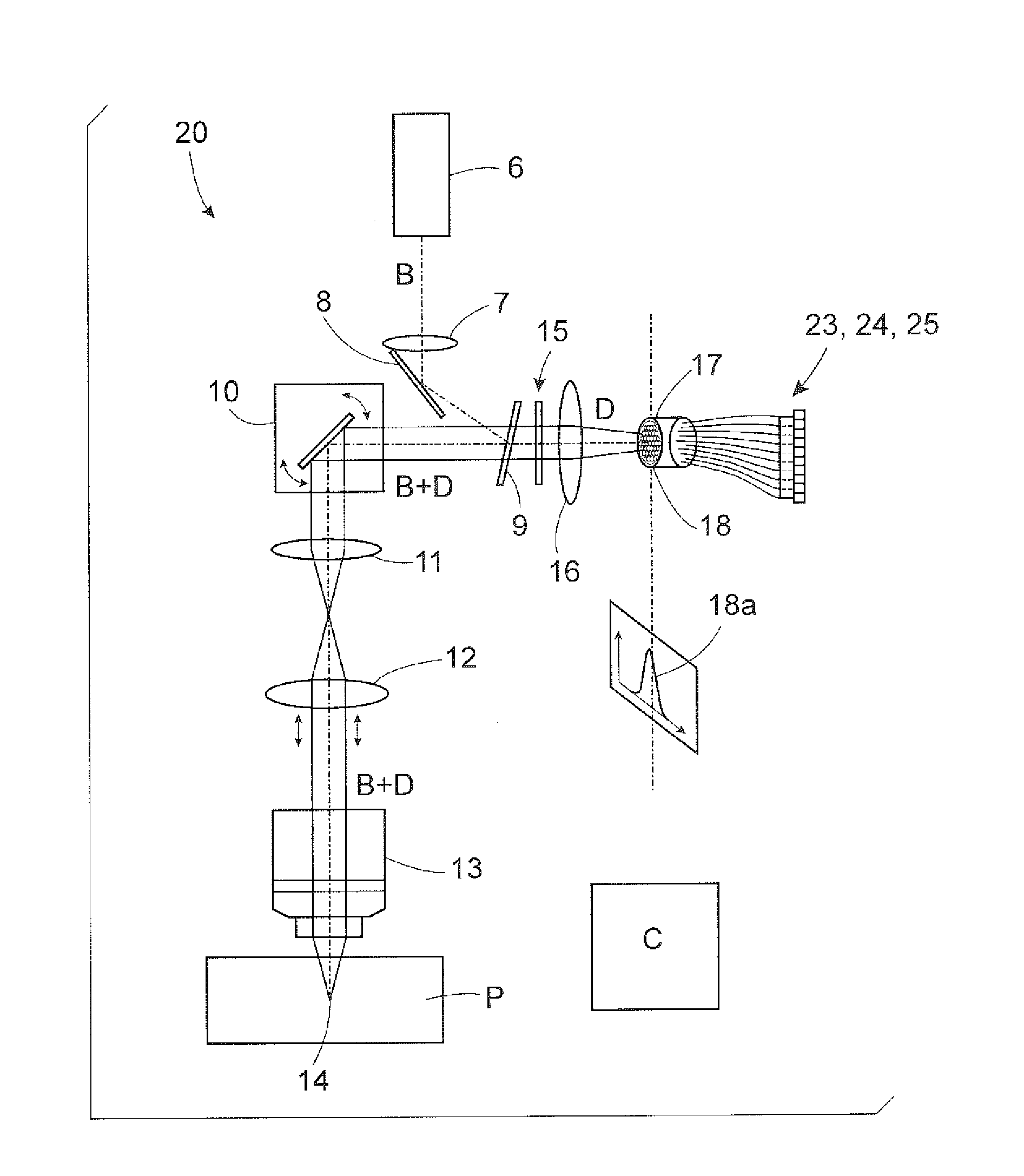
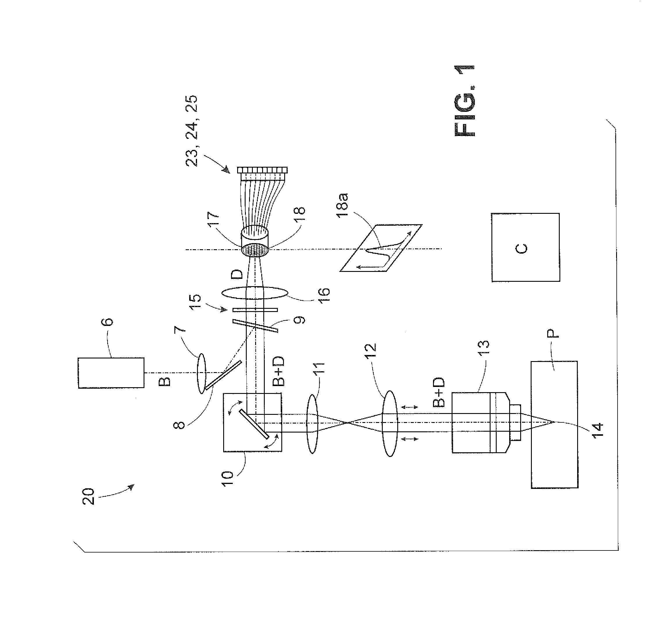
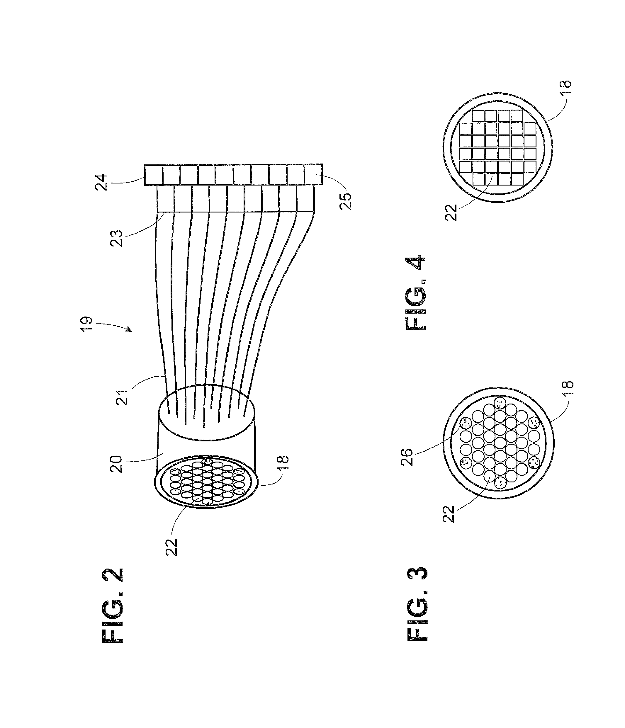
[0041]FIG. 1 schematically shows a laser scanning microscope 1 which is designed for the purpose of microscopy of a sample 2. The laser scanning microscope (abbreviated below as LSM) 1 is controlled by a control device C and comprises an illumination beam path 3 and an imaging beam path 4. The illumination beam path illuminates a spot in the sample 2, and the imaging beam path 4 images this spot, subject to the diffraction limit, for the purpose of detection. The illumination beam path 3 and the imaging beam path 4 share a plurality of elements. However, this is likewise less necessary than a scanned spot illumination of the sample 2. The same could also be illuminated in wide-field.

[0042]The illumination of the sample 2 in the LSM 1 is carried out by means of a laser beam 5 which is coupled into a mirror 8 via a deflection mirror 6, which is not specifically functionally necessary, and a lens 7. The mirror 8 functions so that the laser beam 5 falls on an emission filter 9 at a refl...


PUM


Abstract

A microscope and method for high resolution scanning microscopy of a sample, having an illumination device, an imaging device for the purpose of scanning at least one point or linear spot across the sample and of imaging the point or linear spot into a diffraction-limited, static single image below a reproduction scale in a detection plane. A detector device is used for detecting the single image in the detection plane for various scan positions, with a location accuracy which, taking into account the reproduction scale in at least one dimension / measurement, is at least twice as high as a full width at half maximum of the diffraction-limited single image.

Description

RELATED APPLICATIONS[0001]The present application is a non-provisional application of Provisional Application No. 62 / 025,649 filed on Jul. 17, 2014 and claims priority benefit of German Application No. DE 10 2013 013 792.6 filed on Aug. 15, 2013 and German Application No. DE 10 2013 019 347.8 filed on Nov. 15, 2013, the contents of each are incorporated by reference in their entirety.FIELD OF THE INVENTION[0002]The invention relates to a microscope for high resolution scanning microscopy of a sample, having an illumination device for the purpose of illuminating the sample, an imaging device for the purpose of scanning a point or linear spot across the sample and of imaging the point- or linear spot into a diffraction-limited, resting single image, with a reproduction scale in a detection plane, a detector device for the purpose of detecting the single image in the detection plane for various scan positions, with a location accuracy which, taking into account the reproduction scale, ...

Claims


Application Information

Patent Timeline
IPC IPC(8): G02B21/00G02B15/14G02B6/08H04N7/18G02B21/36
CPCG02B21/0072H04N7/183G02B21/0076G02B21/0032G02B6/08G02B15/14G02B21/361G02B21/008G02B15/142
Inventor KLEPPE, INGONOVIKAU, YAUHENINIETEN, CHRISTOPHNETZ, RALF
Owner CARL ZEISS MICROSCOPY GMBH
Learn More