Strain relief device for low friction drop cable

a technology of strain relief device and drop cable, which is applied in the direction of machine support, electric apparatus casing/cabinet/drawer, other domestic objects, etc., can solve the problem of insufficient strain relief devi

Inactive Publication Date: 2016-05-12
CORNING RES & DEV CORP
View PDF2 Cites 14 Cited by
  • Summary
  • Abstract
  • Description
  • Claims
  • Application Information

AI Technical Summary

Benefits of technology

[0010]In one aspect of the present invention, the strain relief device can be used for both strain and improved handling of low friction drop cables or other difficult to grip cable geometries. The plurality of tie down points on each retention fingers enables these types of drop cables to be gripped more securely with simple fastening members such as cable ties than can be achieved with conventional strain relief devices.

Problems solved by technology

However, these strain relief devices are insufficient for new low friction drop cables or other difficult to grip drop cable geometries utilized in some Fiber to The Home (FTTH) network deployments.

Method used


Image

  • Strain relief device for low friction drop cable
  • Strain relief device for low friction drop cable
  • Strain relief device for low friction drop cable

Examples


Embodiment Construction

[0023]Now reference will be made in detail to exemplary embodiments of the present invention that are illustrated in the accompany drawings, which illustrate specific embodiments in which the invention may be practiced. The illustrated embodiments are not intended to be exhaustive of all embodiments according to the invention. It is to be understood that other embodiments may be utilized and structural or logical changes may be made without departing from the scope of the present invention. Wherever possible, similar reference numbers will be used throughout the drawings to refer to the same or similar parts. The following detailed description, therefore, is not to be taken in a limiting sense, and the scope of the present invention is defined by the appended claims.

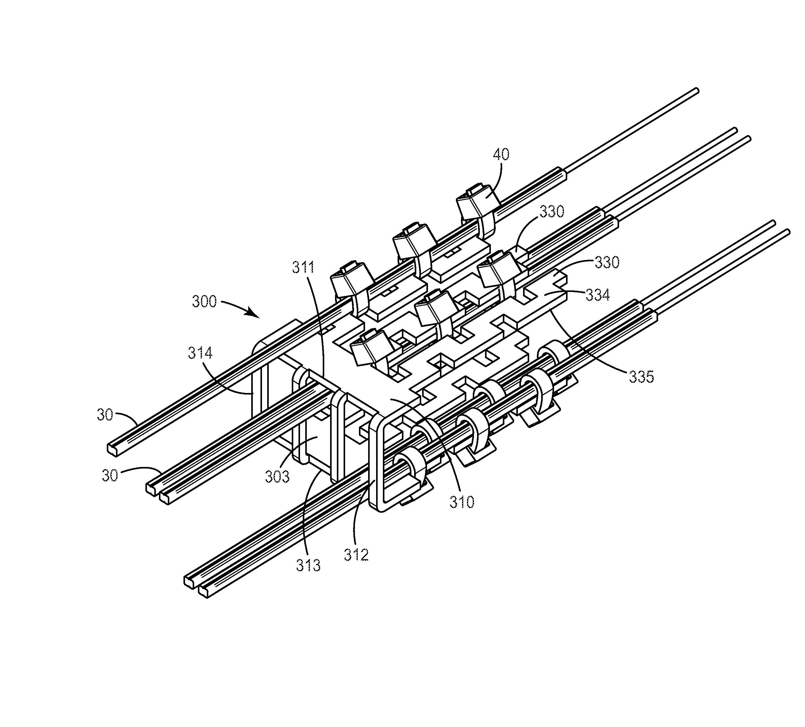
[0024]Fiber to The Home network deployments are selecting application of low friction drop cables including Low Friction FRP Drop cables such as are available from Furukawa Electrical Co., Ltd. or Sumimoto Corporation. T...


PUM


Abstract

The present invention relates to a strain relief device for use in a telecommunication enclosure. The exemplary strain relief device includes a bracket body base and a plurality of retention fingers extending from the bracket body base. Each of the plurality of retention fingers has a series of slots that define a plurality of tie down points for securing a drop cable at a plurality of points along one of the plurality of retention fingers. Each of the plurality of retention fingers has one of a chicane configuration, a serpentine configuration, comb configuration, and a rectangular configuration.

Description

FIELD OF INVENTION[0001]The present invention relates to a device that provides high strain relief for drop cables with low friction coefficient and / or high and dense strain relief as well as easy handling and removing thereof.BACKGROUND OF INVENTION[0002]Cables, such as telecommunication cables and electrical power distribution cables, are ubiquitous and used for distributing electrical power and all manner of data signals across vast networks. The majority of cables are electrically conductive cables (typically copper), although the use of optical fiber cables is growing rapidly in telecommunication systems as larger and larger amounts of data are transmitted. As cables are routed across power or data networks, it is necessary to periodically open, connect, or splice the cable so that power or data may be distributed to other cables or “branches” of the network. The cable branches may be further distributed until the network reaches individual homes, businesses, offices, and so on...

Claims


Application Information

Patent Timeline
Patent Type & Authority Applications(United States)
IPC IPC(8): H02G15/007F16L3/12
CPCF16L3/1222H02G15/007H05K5/0247H02G7/02
Inventor BONVALLAT, PIERRETAMAKI ISHUU, MARCELOBIZARRIA, FELIPE SALGADO RENNO
Owner CORNING RES & DEV CORP
Why Eureka
Try Eureka