Electronic cigarette

a technology of electronic cigarettes and cigarette shells, applied in tobacco, mechanical equipment, container discharge methods, etc., can solve the problem of prone to clogging of ventilation holes

Inactive Publication Date: 2016-05-19
SHENZHEN KIMSEN TECH CO LTD
View PDF19 Cites 48 Cited by
  • Summary
  • Abstract
  • Description
  • Claims
  • Application Information

AI Technical Summary

Benefits of technology

[0020]When implementing the electronic cigarette of the present application, the following advantageous can be achieved: by providing an extension part extending into the interior of the atomizer on the second electrode, and defining at least one first through-hole on a side face of the extension part, it is possible for the second lead wire to be electrically connected to the extension part. Besides, the drawback in the art that the air channel running through the second electrode is clogged by the soldering tin, which is caused by the second lead wire soldered on the second electrode, is avoided. During smoking, the electronic cigarette of the present application has smooth ventilation.

Problems solved by technology

When soldering lead wires of the atomizing element, the ventilation hole is prone to be clogged by soldering tin for the electronic cigarette with this configuration, since the ventilation hole runs through the second electrode along the axial direction thereof.

Method used


Image

  • Electronic cigarette
  • Electronic cigarette
  • Electronic cigarette

Examples


embodiment one

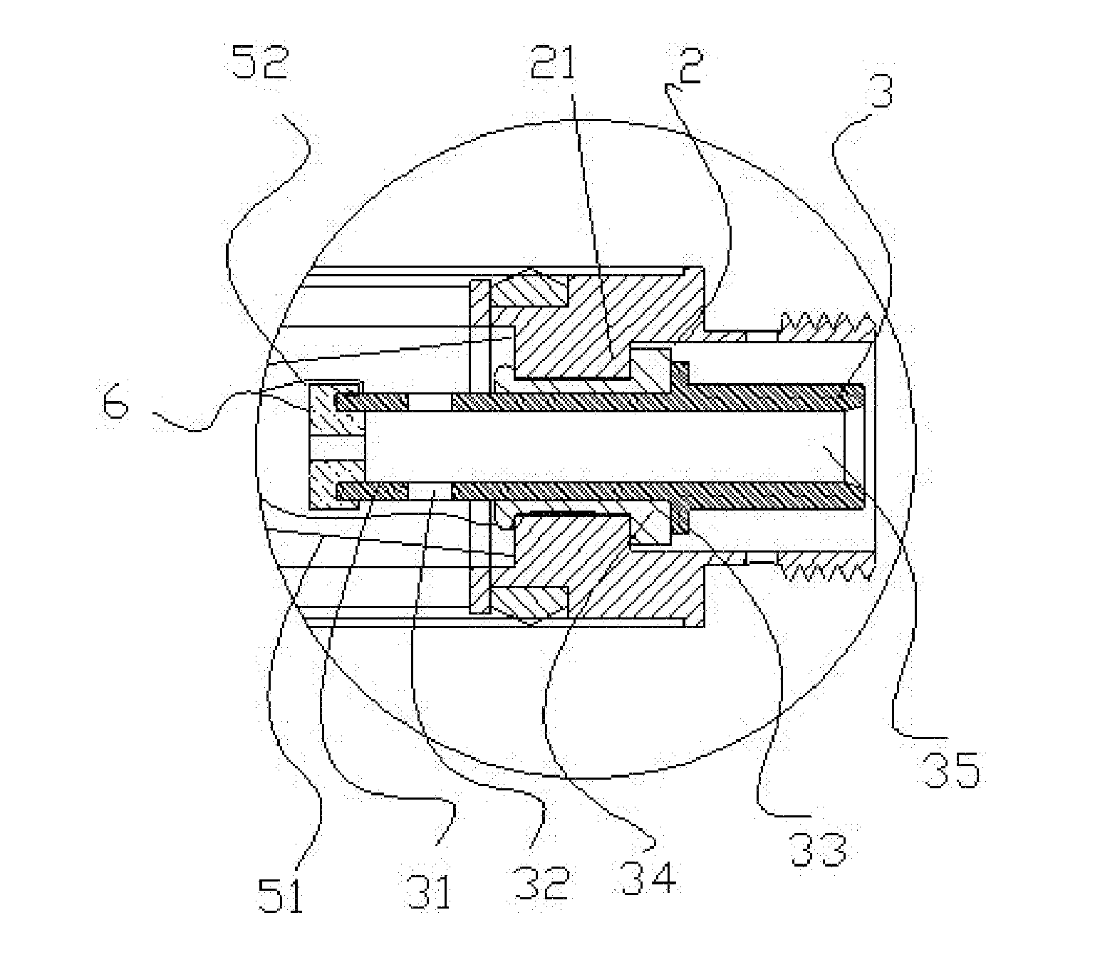
[0039]As shown in FIGS. 5-8, a clamping element 6 is sleeved on an end portion of the extension part 31. The second lead wire 52 is clamped between the extension part 31 and the clamping element 6, and is further electrically connected to the second electrode 3.

[0040]A blind hole is axially defined on the end portion of the extension part 31. The clamping element 6 is an element having an “E”-shaped axial section matching with the blind hole. Or, the first air channel 35 runs through two ends of the second electrode 3, and a second through-hole communicated with the first air channel 35 runs through the clamping element 6 along an axial direction of the clamping element. The clamping element 6 is an element having an “E”-shaped axial section, and the second through-hole axially runs through the middle of the “E”-shaped element (as shown in FIG. 8 specifically).

[0041]At this time, the first lead wire 51 is clamped between the insulating ring 34 and the first electrode 2. The clamping...

embodiment two

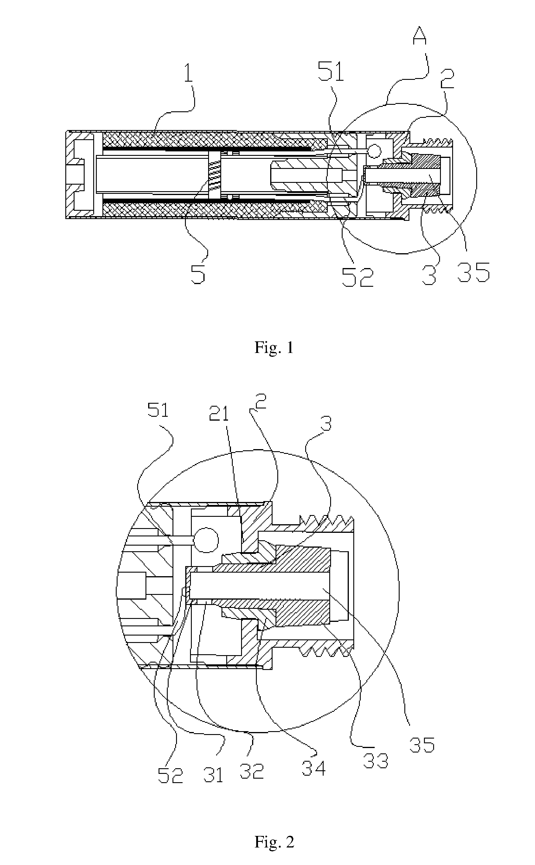
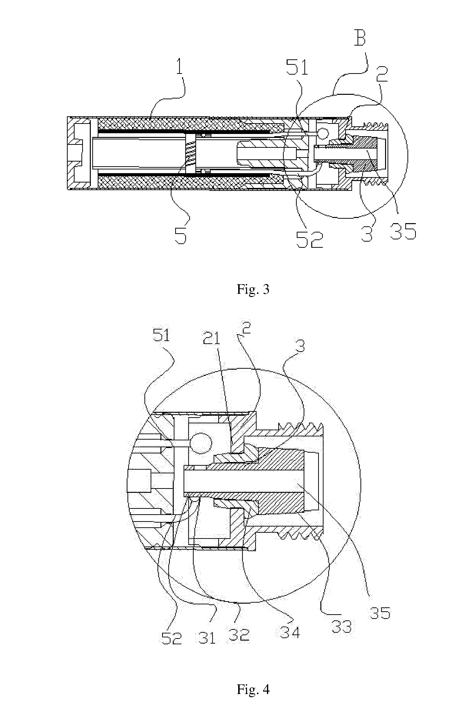
[0044]As shown in FIGS. 1-4, the second lead wire 52 is connected to the extension part 31 by means of soldering.

[0045]Implementing Method One: As shown in FIGS. 1-2, an end face of the extension part 31 is closed, and the second lead wire 52 is soldered to the end face of the extension part 31. At this time, since the second lead wire 52 is soldered to the end face of the extension part 31, and the first through-hole 32 is defined on a side face of the extension part 31, a clogging of the ventilation hole will not occur since the soldering tin is at a large distance from the first through-hole 32. Preferably, in this case, there are two first through-holes 32.

[0046]Implementing Method Two: As shown in FIGS. 3-4, the first air channel 35 runs through two ends of the second electrode 3. The second lead wire 52 is soldered on the side face of the extension part 31, and the second lead wire 52 and the first through-hole 32 are staggered from each other. In this case, a clogging of the ...


PUM


Abstract

An electronic cigarette is provided, which comprises an atomizer, and a first electrode and a second electrode which are inserted in an end portion of the atomizer; wherein the atomizer is further provided therein with an atomizing element for atomizing tobacco tar, and a first lead wire and second lead wire which are electrically connected to the atomizing element; the second electrode has an extension part that extends into the interior of the atomizer; the second lead wire is electrically connected to the extension part, and the first lead wire is electrically connected to the first electrode. At least one first through-hole allowing airflow to pass through is defined on a side face of the extension part. In the electronic cigarette, a clogging phenomenon is not easy to occur when the second lead wire is electrically connected to the second electrode by means of soldering.

Description

TECHNICAL FIELD[0001]The present application relates to the technical field of electrical heating products, and more particularly, relates to an electronic cigarette.BACKGROUND[0002]In the prior art, a typical electronic cigarette includes an atomizer and a first electrode connected to the atomizer. An insulating ring and a second electrode are respectively sleeved inside the first electrode. An atomizing element is further provided in the atomizer, wherein a negative pole of the atomizing element is electrically connected to the second electrode, while a positive pole of the atomizing element is electrically connected to the first electrode. A ventilation hole runs through the second electrode, and the negative pole of the atomizing element is connected to an end face of the second electrode by means of soldering. When soldering lead wires of the atomizing element, the ventilation hole is prone to be clogged by soldering tin for the electronic cigarette with this configuration, sin...

Claims


Application Information

Patent Timeline
Patent Type & Authority Applications(United States)
IPC IPC(8): A24F47/00A24F40/10A24F40/485A24F40/50
CPCA24F47/002A24F47/008A24F40/10A24F40/50A24F40/485
Inventor LIU, QIUMING
Owner SHENZHEN KIMSEN TECH CO LTD
Why Eureka
Try Eureka