Clamp apparatus
a technology of clamping apparatus and clamping rod, which is applied in the direction of positioning apparatus, metal-working machine components, manufacturing tools, etc., can solve the problems of large installation space and increased installation costs, and achieve the effect of reducing installation costs, ensuring stability and reliability, and reducing installation costs
- Summary
- Abstract
- Description
- Claims
- Application Information
AI Technical Summary
Benefits of technology
Problems solved by technology
Method used
Image

Examples
first embodiment
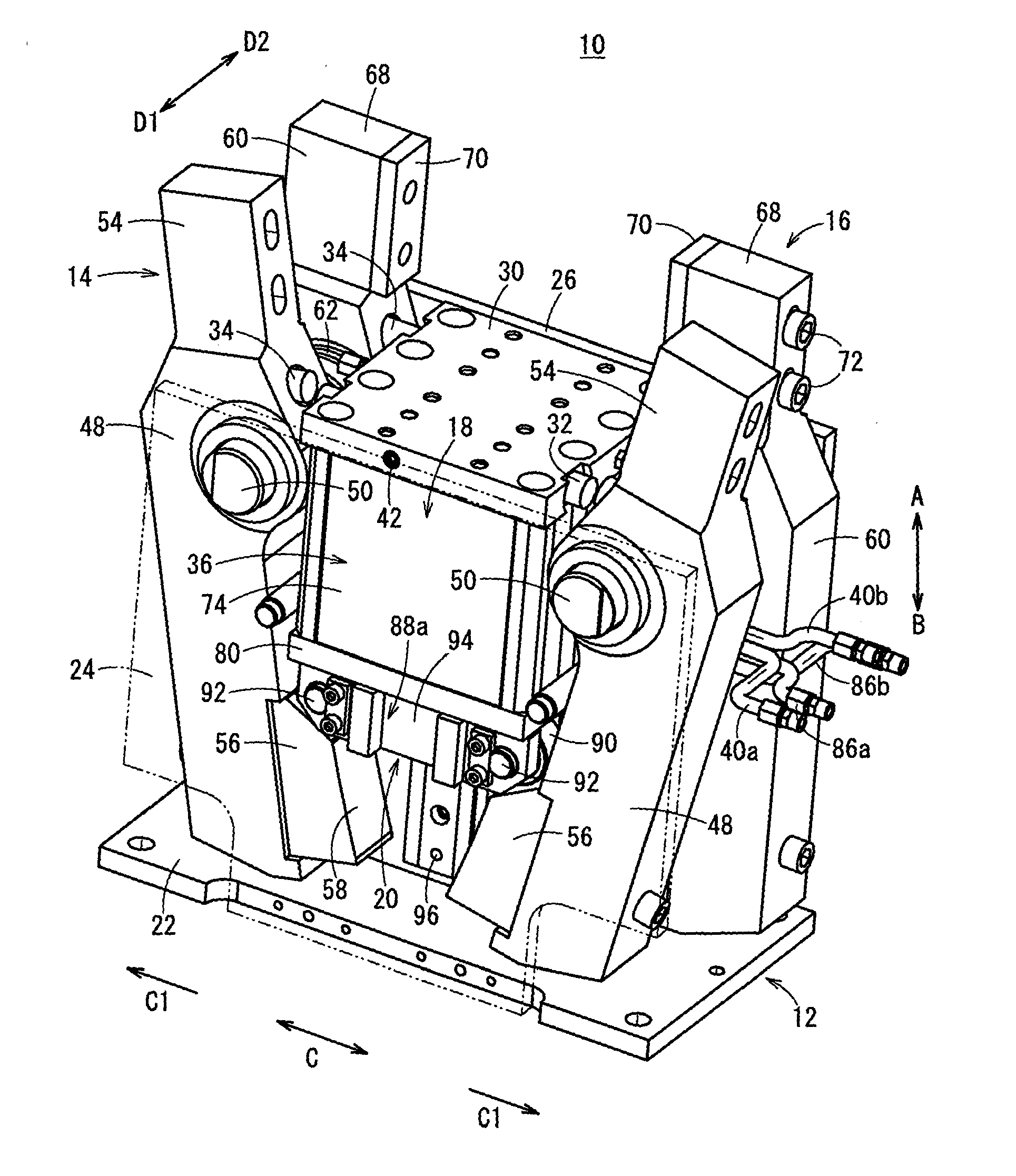
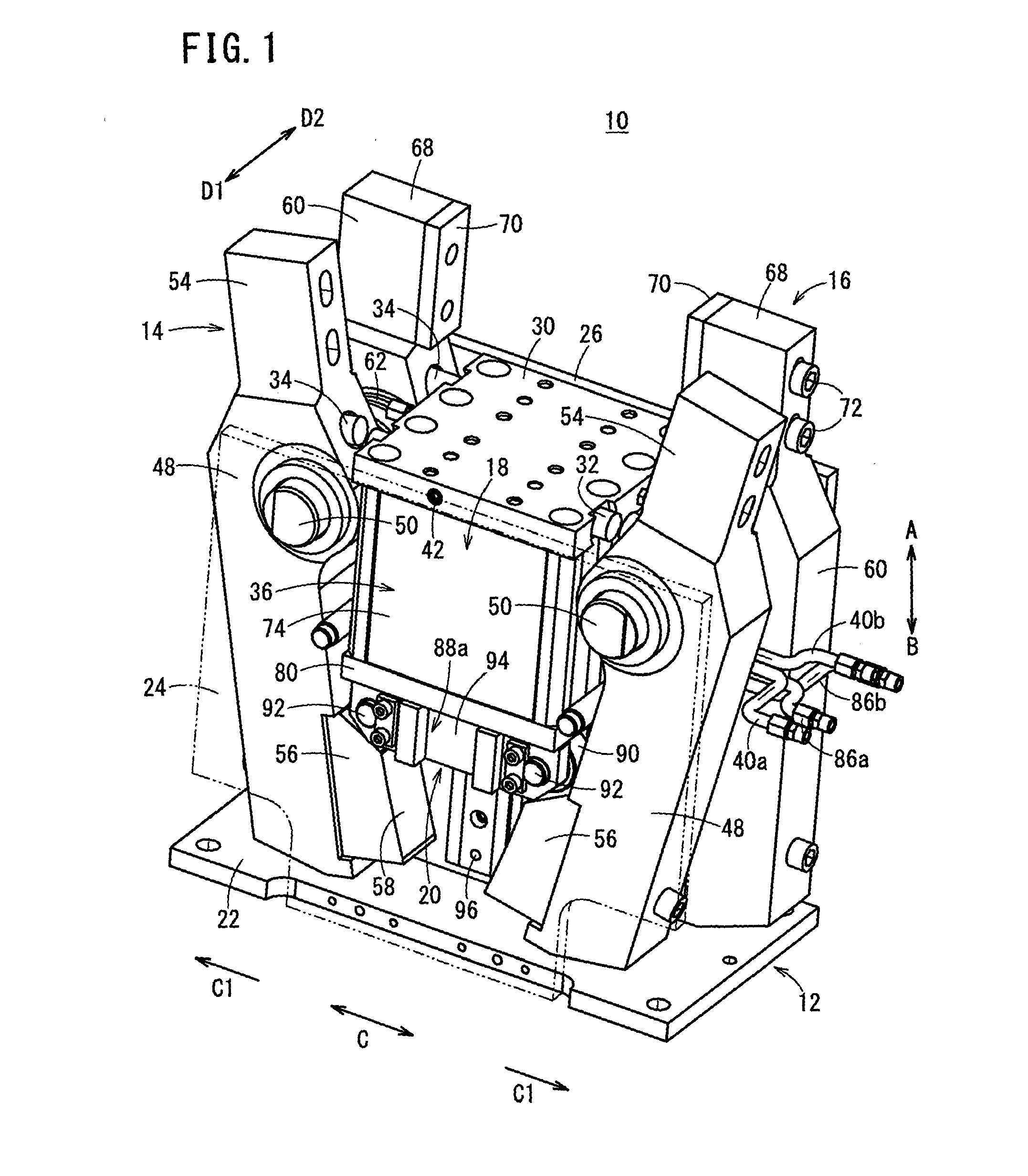
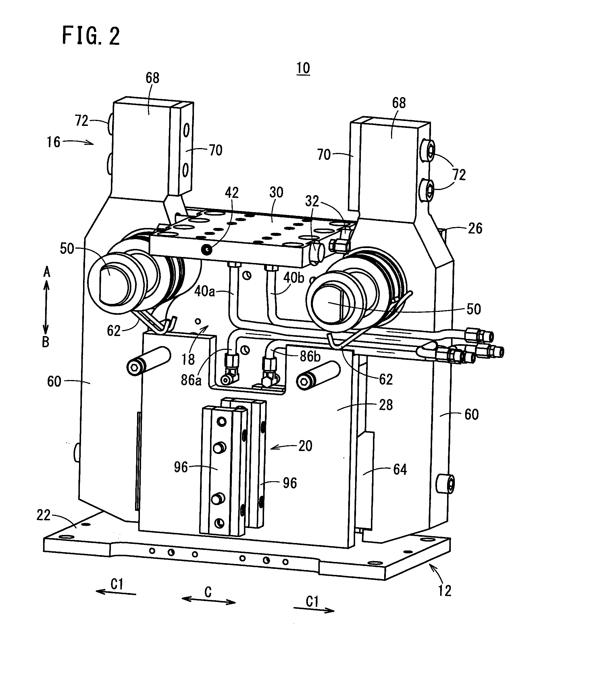
[0083]The clamp apparatus 10 according to the present invention is constructed basically as described above. Next, operations and advantages of the clamp apparatus 10 will be explained. In the following description, the unclamped condition shown in FIG. 3, in which the first and second gripping members 54, 68 of the first and second clamp arms 14, 16 are separated respectively from each other, will be described as an initial position.
[0084]At first, the initial position in the unclamped state will be described. In the initial position, as shown in FIG. 3, pressure fluid is not supplied with respect to the first and second cylinders 36, 38 that make up the drive units 18, and a condition is assumed in which the other ends of the first and second clamp arms 14, 16 are biased in directions (the directions of the arrows E1) away from each other by the spring forces of the first and second springs 52, 62. Further, the pistons 76 and the piston rods 78 are raised in a condition such that ...
second embodiment
[0142] as described above, in the clamp apparatus 100, the link plates 104 of the assist mechanism 102 are disposed rotatably between the one ends of the first and second clamp arms 14, 16 and the rollers 90 that are pivotally supported on the block bodies 88a, 88b. Owing thereto, when the first and second clamp arms 14, 16 are subjected to the unclamping operation, if for some reason the load thereon is large and the unclamping operation is incapable of being performed solely with the spring forces of the first and second springs 52, 62, by rotation of the link plates 104, a pressing force can be imparted in a widthwise inward direction through the link pins 106 to the one end sides of the first and second clamp arms 14, 16.
[0143]As a result, even if for some reason the unclamping operation of the first and second clamp arms 14, 16 cannot be carried out, by rotating the link plates 104 of the assist mechanism 102 under a driving action of the drive unit 18, and thereby pressing the...
third embodiment
[0163] as described above, for example, the release levers 154 that constitute the manual release mechanism 152 are disposed rotatably on outer sides of the first and second plate bodies 24, 26 that make up the body 12. Further, even in a condition in which supply of pressure fluid to the drive unit 18 is suspended, and the clamped state of the first workpiece W1 or the second workpiece W2 is locked, by operation of the release levers 154, the connecting pins 158 connected to the roller pins 92 can be pressed upwardly.
[0164]Therefore, the rollers 90, which are in abutment against the first and second cam members 56, 64 and are pressing the first and second clamp arms 14, 16 in widthwise outside directions, can easily and reliably be moved upwardly (in the direction of the arrow A) along the cam surfaces 58, 66, so that the first and second clamp arms 14, 16 can be unclamped easily and reliably by the spring forces of the first and second springs 52, 62.
[0165]Further, with a simple s...
PUM
 Abstract
Description
Claims
Application Information
 - R&D
- Intellectual Property
- Life Sciences
- Materials
- Tech Scout
- Unparalleled Data Quality
- Higher Quality Content
- 60% Fewer Hallucinations
Browse by: Latest US Patents, China's latest patents, Technical Efficacy Thesaurus, Application Domain, Technology Topic, Popular Technical Reports.
© 2025 PatSnap. All rights reserved.Legal|Privacy policy|Modern Slavery Act Transparency Statement|Sitemap|About US| Contact US: help@patsnap.com