Assisted propulsion system, method and chassis

a propulsion system and chassis technology, applied in the direction of wheelchair/patient conveyance, electric devices, jet propulsion mounting, etc., can solve the problems of reducing the risk of injury to the care giver, the risk of slips, falls, strains and knocks on the patient, and the introduction of such equipment is not without its problems, so as to achieve the effect of convenient and predictable control

Active Publication Date: 2016-05-19
ARJO IP HLDG AB
View PDF3 Cites 27 Cited by
  • Summary
  • Abstract
  • Description
  • Claims
  • Application Information

AI Technical Summary

Benefits of technology

[0062]In embodiments of the present invention, the assisted propulsion system is arranged to sense and take the flooring properties into account to work consistently in different environments such as between very soft flooring and very hard flooring. Advantageously, offering a consistent experience to the operator is not only more pleasant for the operator, it also means that the equipment is safer to convey and more predictable to control (as the operator does not need to account of flooring type when determining how hard to push, for example).
[0065]When using Mecanum wheels for giving omni directional properties to a platform it is common practice to use a set of four wheels distributed in the four corners of a chassis. In contrast, preferred embodiments of the present invention include only two Mecanum wheels and thus advantageously reduce the cost and complexity of the power assisted propulsion system. The reduction of number of Mecanum wheels used from the typical four to two has a direct impact, reducing the cost and complexity of such a system and meaning that power assisted propulsion systems become economically viable for more uses / equipment types.
[0067]In one embodiment of the present invention, a system is provided in which a payload is transported on or in a chassis is supported by wheels of the chassis such as castors. A drive that is preferably independent of the wheels is provided to propel the chassis in one or more of multiple directions at any one time, such as using one or more powered Mecanum wheels. The drive is decoupled from the payload of the chassis. Advantageously, such a system benefits from the multi directional drive capabilities of the Mecanum wheel whilst avoiding exposing the payload to the ‘bumpy’ ride inherent in systems that use Mecanum wheels.

Problems solved by technology

However, balancing these desires in a system that can convey the intended payloads in the particular environment is often challenging.
Manual handling of patients exposes care givers to dangerously high strains, especially in their lower backs, resulting in possible injuries.
Proper use of such equipment can significantly lower the risk for injury to the care giver and also of risk of slips, falls, strains and knocks to the patient.
However, the introduction of such equipment is not without its issues.
It is well known for manual hospital beds and the like to be heavy, difficult to start moving or stop, difficult to direct and have “minds of their own”, despite the best efforts of its operator pushing in the desired direction.
Additionally, equipment that may be useful in a hospital environment may not be suitable for use in a residential environment, for example, meaning that different equipment may be needed in different environments despite being used for the same or similar purpose.
While generally helpful, such systems often do not provide propulsion in all directions that the chassis can be moved in.

Method used


Image

  • Assisted propulsion system, method and chassis
  • Assisted propulsion system, method and chassis
  • Assisted propulsion system, method and chassis

Examples


Embodiment Construction

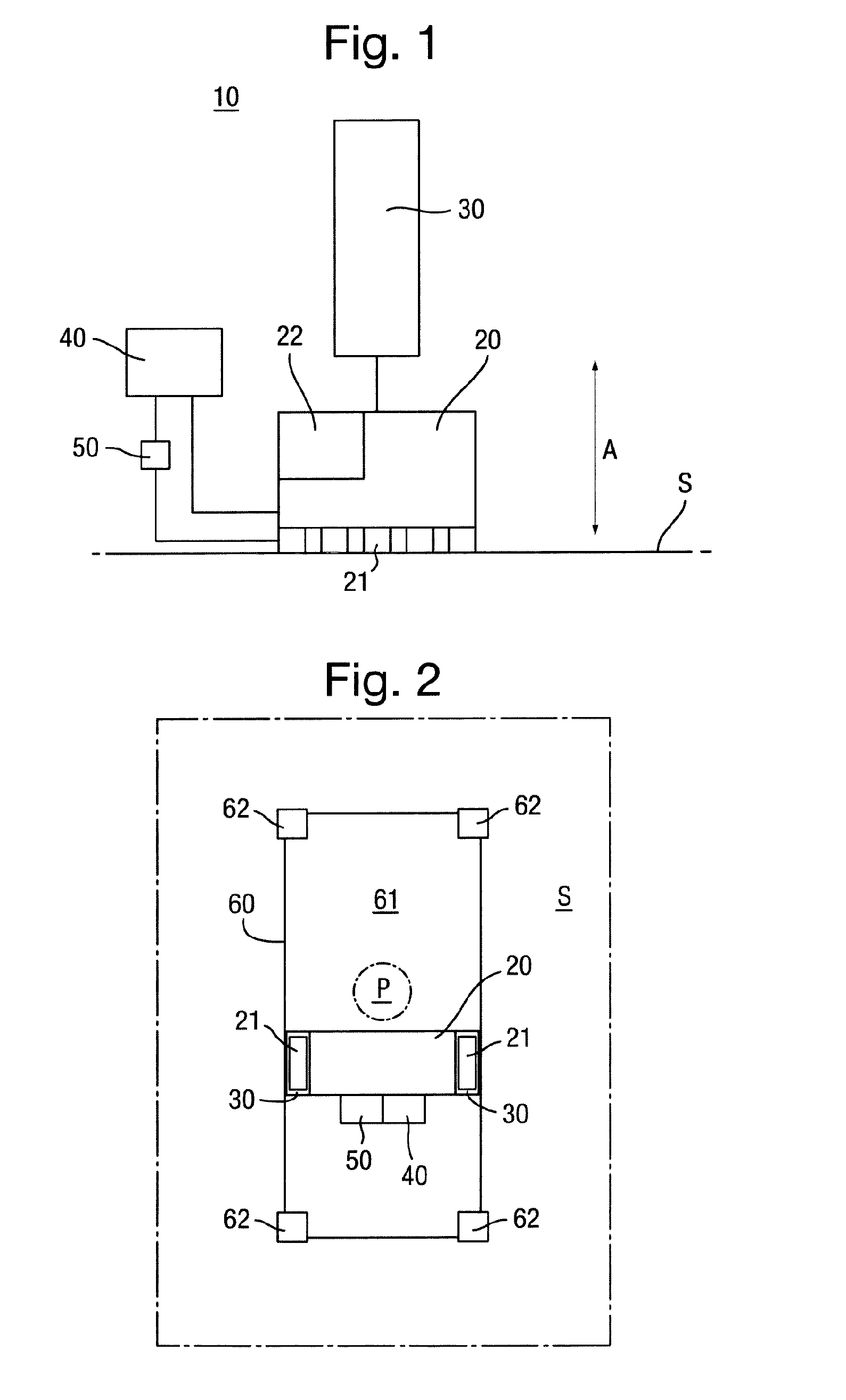
[0080]FIG. 1 is a schematic diagram of an assisted propulsion system for a wheeled chassis according to an embodiment of the present invention.

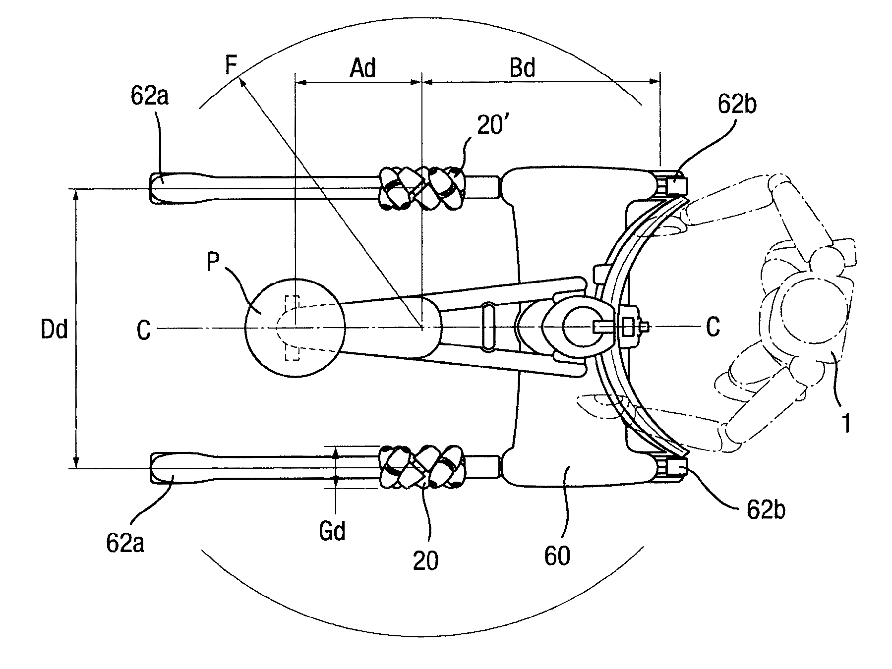
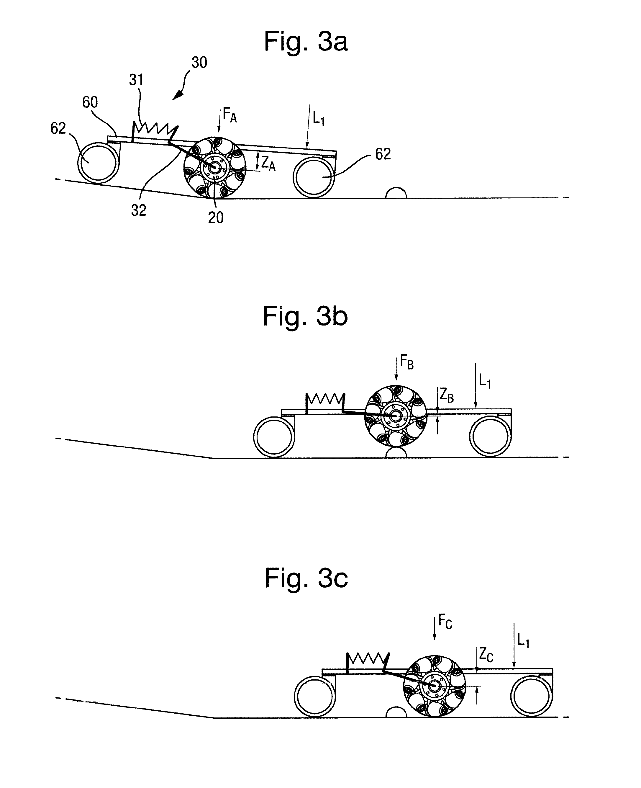
[0081]The assisted propulsion system 10 includes a drive 20 coupleable to a chassis via a mount 30 as shown in FIGS. 2 and 3a-3c. The assisted propulsion system 10 is arranged to provide assisted propulsion to the chassis along the surface S.

[0082]The mount 30 substantially decouples at least a driving part 21 of the drive from the chassis in a direction A substantially perpendicular to the surface S and is arranged to apply a resilient spring force to direct at least the driving part 21 of the drive onto the surface S during provision of said assisted propulsion.

[0083]The assisted propulsion system includes a controller 40 arranged to control operation of the drive, the drive being preferably free to move under external forces when not under control of the controller (so it can be manually pushed and will not substantially resist, for exampl...


PUM


Abstract

An assisted propulsion system, method and chassis for conveying a payload along a surface are described. A plurality of wheels disposed about the chassis support it on the surface. A drive provides at least assisted propulsion to the chassis along the surface. At least a driving part of the drive is connected to the chassis via a mount having a resiliently sprung link. At least the driving part of the drive has a fixed orientation and is moveable independently of the chassis and the plurality of wheels in a direction towards the surface. The resiliently sprung link is arranged to direct at least the driving part onto the surface during provision of the assisted propulsion. A sensor is arranged to monitor acceleration of the drive and to communicate data on acceleration to a controller, which controls operation of the drive in dependence on the data received from the sensor.

Description

FIELD OF THE INVENTION[0001]The present invention relates to a chassis having an assisted propulsion system and to an assisted propulsion system and method that is particularly applicable for use in providing assisted propulsion in manual transport operations such as movement of payloads such as boxes, people, animals and the like.BACKGROUND TO THE INVENTION[0002]Payload transport systems vary greatly in size, payload capacity and complexity. Manually operated payload transport systems are generally designed to be easy to use, controllable and responsive. However, balancing these desires in a system that can convey the intended payloads in the particular environment is often challenging.[0003]Take, for example, patient handling and transportation in healthcare environments. Manual handling of patients exposes care givers to dangerously high strains, especially in their lower backs, resulting in possible injuries. For this reason, patient handling equipment for the transfer of a pati...

Claims


Application Information

Patent Timeline
Patent Type & Authority Applications(United States)
IPC IPC(8): B62B5/00A61G7/10A61G7/08
CPCB62B5/0073B62B5/0026A61G7/1046A61G7/1023A61G7/08A61G7/1048A61G2203/10A61G2203/36B60L15/20B60L2200/24B60L2240/12B60L2240/14B60L2240/423B60L2240/662B60L2220/50Y02T90/16Y02T10/72B62B5/0069B62B3/001B62B3/008B62B2301/25B60L50/52Y02T10/64Y02T10/70
Inventor NILSSON, RICHARDJONSSON, JORGEN
Owner ARJO IP HLDG AB
Why Eureka
Try Eureka