
Micro hybrid generator system drone

a generator system and hybrid technology, applied in the direction of vehicle position/course/altitude control, process and machine control, instruments, etc., can solve the problems of high maintenance cost, difficult operation of single rotor aerial vehicles, and difficult diagnosis of problems

Active Publication Date: 2016-05-19
ISTARI
View PDF11 Cites 127 Cited by
  • Summary
  • Abstract
  • Description
  • Claims
  • Application Information

AI Technical Summary

Benefits of technology

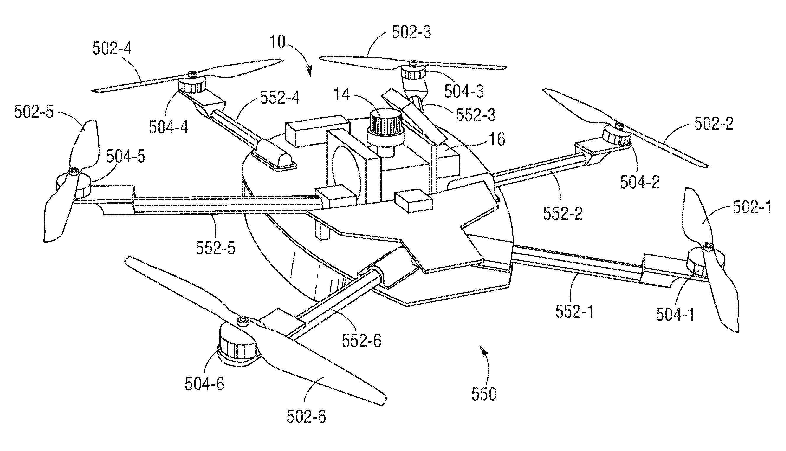
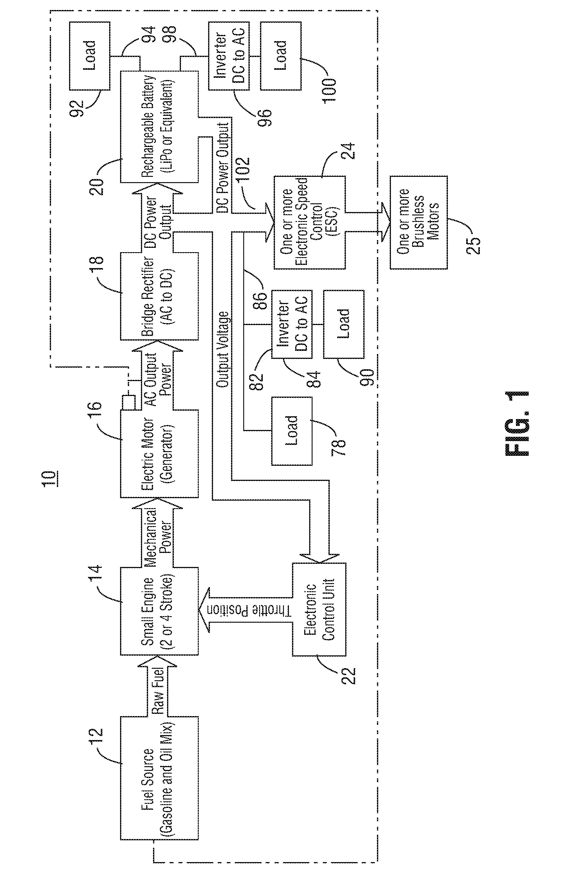
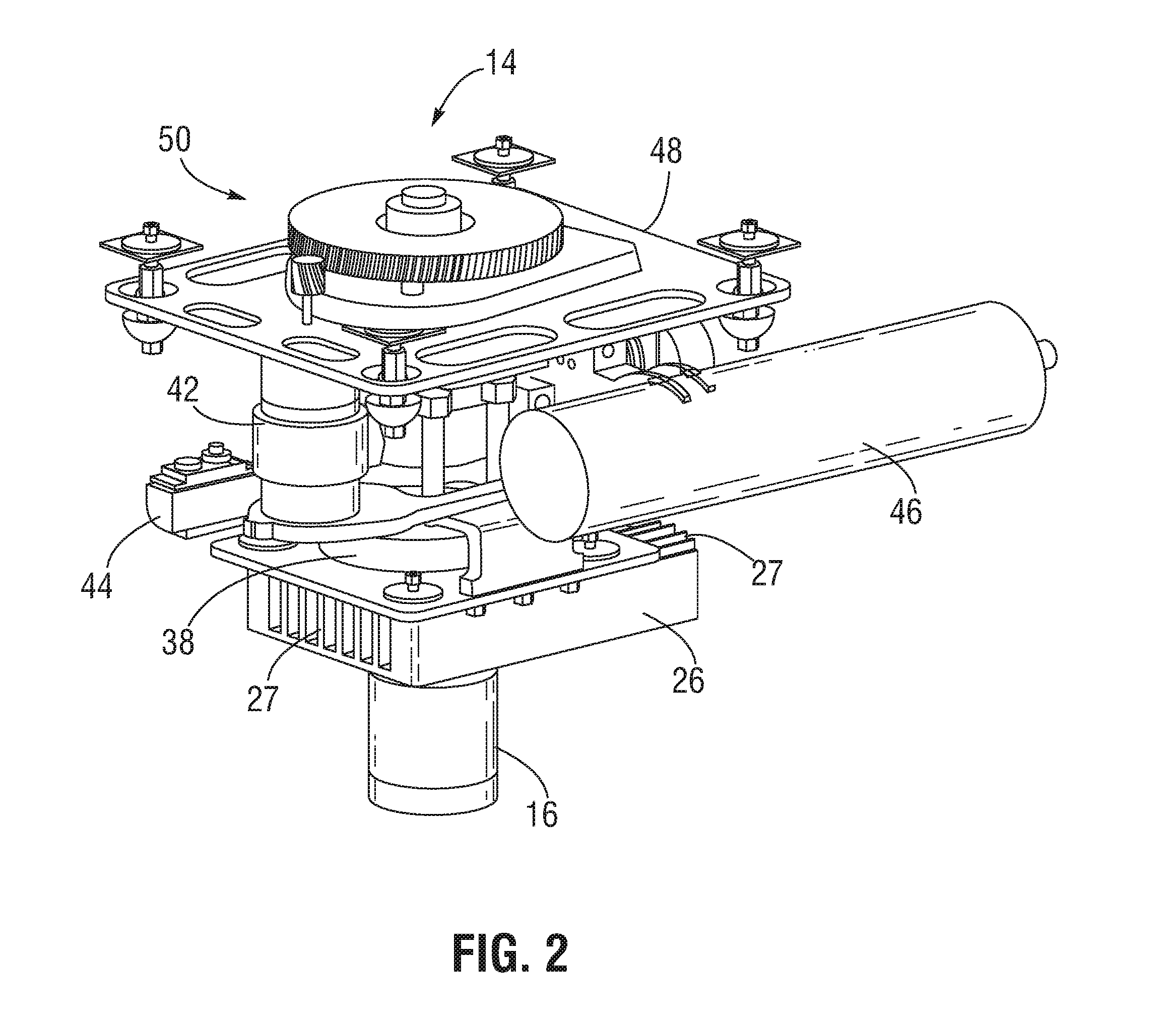
The patent describes various configurations and aspects of drones, which are unmanned aerial vehicles. The drones have a rotor motor to generate thrust and fly. Some drones have a speed control system to manage the motor's power. Some drones have a small engine or a rechargeable battery to provide power to the motor. Some drones have a generator motor and a bridge rectifier to generate and convert AC power. Some drones have an electronic control unit to manage the engine's power demand. These configurations and methods have been developed to address different problems and improve drone performance.

Problems solved by technology

Additionally, single rotor aerial vehicles are also notoriously difficult to operate, diagnose problems, and are expensive to maintain.
Thus, when the battery is depleted, the UAV will stop operating.
If the UAV is in flight, this can result in a catastrophic crashing of the UAV.
Additionally, if aggressive maneuvers are needed during flight, such as quickly veering away from an object or moving quickly to avoid a potential threat, such maneuvers require instantaneous peak power which can quickly deplete the battery and significantly reduce flight time significantly.
Thus, conventional battery powered multi-rotor UAVs have limited endurance and payload and provide no backup power in the event the battery supply is depleted.
Additionally, conventional commercial UAVs are very expensive and not commercially viable at scale today.
Conventional portable generators are heavy and may be difficult to transport to desired locations.

Method used


Image

  • Micro hybrid generator system drone
  • Micro hybrid generator system drone
  • Micro hybrid generator system drone

Examples


Embodiment Construction

[0032]Aside from the preferred embodiment or embodiments disclosed below, this invention is capable of other embodiments and of being practiced or being carried out in various ways. Thus, it is to be understood that the invention is not limited in its application to the details of construction and the arrangements of components set forth in the following description or illustrated in the drawings. If only one embodiment is described herein, any claims based on this provisional patent application are not to be limited to that embodiment. Moreover, any such claims are not to be read restrictively unless there is clear and convincing evidence manifesting a certain exclusion, restriction, or disclaimer.

[0033]One or more embodiments of a micro hybrid generator system provide a small portable micro hybrid generator power source with energy conversion efficiency. In UAV applications, the micro hybrid generator system of one or more embodiments can be used to overcome the weight of the vehi...


PUM


Abstract

An unmanned aerial vehicle comprising at least one rotor motor. The rotor motor is powered by a micro hybrid generation system. The micro hybrid generator system comprises a rechargeable battery configured to provide power to the at least one rotor motor, a small engine configured to generate mechanical power, a generator motor coupled to the small engine and configured to generate AC power using the mechanical power generated by the small engine, a bridge rectifier configured to convert the AC power generated by the generator motor to DC power and provide the DC power to either or both the rechargeable battery and the at least one rotor motor, and an electronic control unit configured to control a throttle of the small engine based, at least in part, on a power demand of at least one load, the at least one load including the at least one rotor motor.

Description

[0001]This application claims priority to U.S. Provisional Application No. 62 / 079,866, filed on Nov. 14, 2014, U.S. Provisional Application No. 62 / 079,890, filed on Nov. 14, 2014, U.S. Provisional Application No. 62 / 080,482, filed on Nov. 17, 2014, and U.S. Provisional Application No. 62 / 080,554, filed on Nov. 17, 2014, each of which is incorporated by reference in its entirety.FIELD OF THE INVENTION[0002]This invention relates to a micro hybrid generator system drone.BACKGROUND OF THE INVENTION[0003]A typical conventional multi-rotor UAV is significantly less complex, easier to operate, less expensive, and easier to maintain than a typical conventional single rotor aerial vehicle, such as a helicopter or similar type aerial vehicle. For example, a conventional multi-rotor UAV may include four or more rotor motors, four or more propellers coupled thereto, four or more electronic speed controllers, a flight control system (auto pilot), an RC radio control, a frame, and a rechargeable...

Claims


Application Information

Patent Timeline
IPC IPC(8): B64D27/02B64D33/08B64C39/02B64C27/00B64C27/08
CPCB64D27/02B64C27/001B64D2027/026B64C39/024B64D33/08B64C27/08G05D1/101B64D27/24Y02T50/60Y02T50/40B64U50/11B64U50/19B64U10/16B64U50/30B64D27/026B64D1/08B64D1/22B64D2221/00B64F3/02
Inventor PHAN, LONG N.SARMA, SANJAY EMANIWOJCIK, CODY MILESDAVIS, ELI M.SENA, BENJAMIN ARTHURLEMUS, JULIAN
Owner ISTARI
Learn More