Fuel delivery system with partial pressure relief valve on the drive line of a suction jet pump
- Summary
- Abstract
- Description
- Claims
- Application Information
AI Technical Summary
Benefits of technology
Problems solved by technology
Method used
Image
Examples
Embodiment Construction
[0033]All drawings are only schematic depictions of devices according to the invention or, respectively of constituent parts thereof according to exemplary embodiments of the invention.
[0034]Particularly spacings and size relations are not reflected true to scale in the figures. Corresponding elements are provided with the same reference numerals in the different drawings.
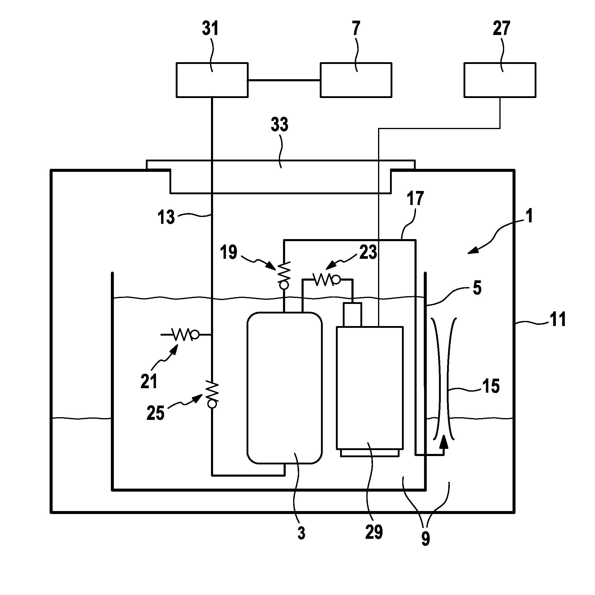
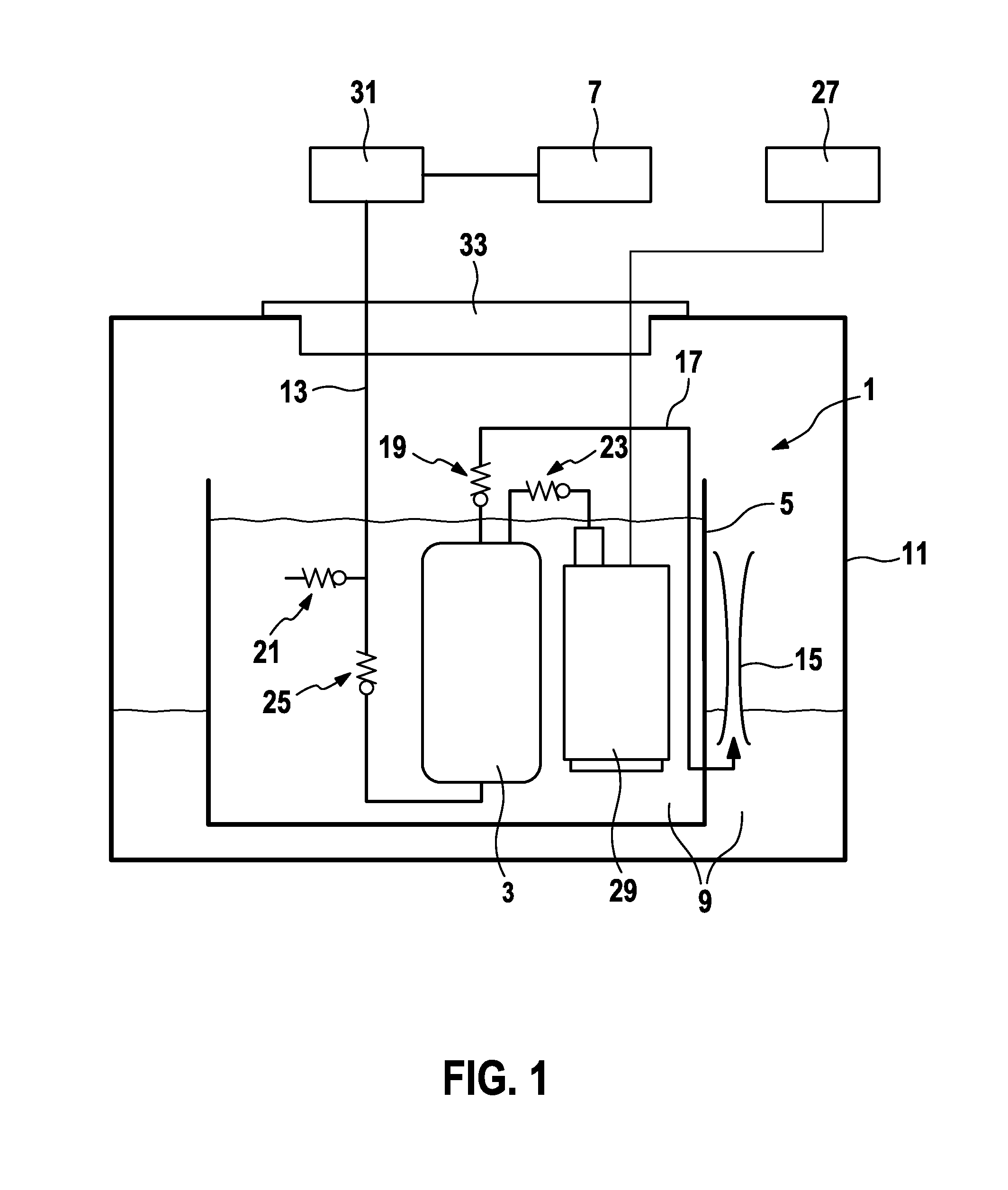
[0035]In FIG. 1, the fuel delivery system 1 is disposed at an accumulator pot 5 in a fuel tank 11. The accumulator pot 5 is disposed as close as possible to the bottom of the fuel tank 11 and accumulates fuel 9 in order to ensure a supply of fuel 9 to the internal combustion engine 7 even when traversing curves and when the resulting sloshing movements of the fuel 9 in the fuel tank 11 occur.
[0036]The fuel delivery system 1 comprises a fuel filter 3, a fuel pump 29 and a suction jet pump 15. The fuel pump 29 delivers fuel 9 from the accumulator pot 5 to the internal combustion engine 7. In so doing, the fuel 9 pass...
PUM
 Abstract
Description
Claims
Application Information
 - R&D
- Intellectual Property
- Life Sciences
- Materials
- Tech Scout
- Unparalleled Data Quality
- Higher Quality Content
- 60% Fewer Hallucinations
Browse by: Latest US Patents, China's latest patents, Technical Efficacy Thesaurus, Application Domain, Technology Topic, Popular Technical Reports.
© 2025 PatSnap. All rights reserved.Legal|Privacy policy|Modern Slavery Act Transparency Statement|Sitemap|About US| Contact US: help@patsnap.com


