Splicing backplane for backlight module and backlight module employing same

a backplane and backlight technology, applied in the field of backlight modules, can solve the problems affecting the reliability and economics of the backplane, and achieve the effects of reducing the difficulty of splicing and the production cost, improving assembly efficiency and product yield, and convenient assembly and disassembly

Active Publication Date: 2016-05-19
TCL CHINA STAR OPTOELECTRONICS TECH CO LTD
View PDF1 Cites 1 Cited by
  • Summary
  • Abstract
  • Description
  • Claims
  • Application Information

AI Technical Summary

Benefits of technology

[0011]Compared with the prior art, a plurality of the splicing backplanes are superposed with each other and combined into one, and the height differences between the mounting portions and the supporting portions of two adjacent backplanes are unequal, so that one backplane can be accommodated into the other backplane; and meanwhile, after the superposition, the overall thickness of the backplanes is invariable. In addition, by adoption of the fastener to fix the two superposed backplanes together, the splicing backplane for the backlight module has the advantages of not destroying the structure of the backplanes, being convenient in assembly and disassembly, reducing the splicing difficulty and the production cost and improving the assembly efficiency and the product yield. Moreover, by the mutual superposition of a plurality of the backplanes, a large-size backplane is not required to be prepared. Furthermore, due to the splicing structure, the supporting intensity of the backplane may be also improved. Meanwhile, the horizontal reinforcing supports and the vertical reinforcing supports which are mutually staggered are additionally arranged and integrated into a whole with the backplane so as to further reinforce the overall intensity of the backplane.

Problems solved by technology

In addition, due to the relatively large weight of the large-size LCD modules, the splicing mode of the backplanes is particularly important and directly affects the reliability and the economy of the backplanes.

Method used


Image

  • Splicing backplane for backlight module and backlight module employing same
  • Splicing backplane for backlight module and backlight module employing same
  • Splicing backplane for backlight module and backlight module employing same

Examples


Embodiment Construction

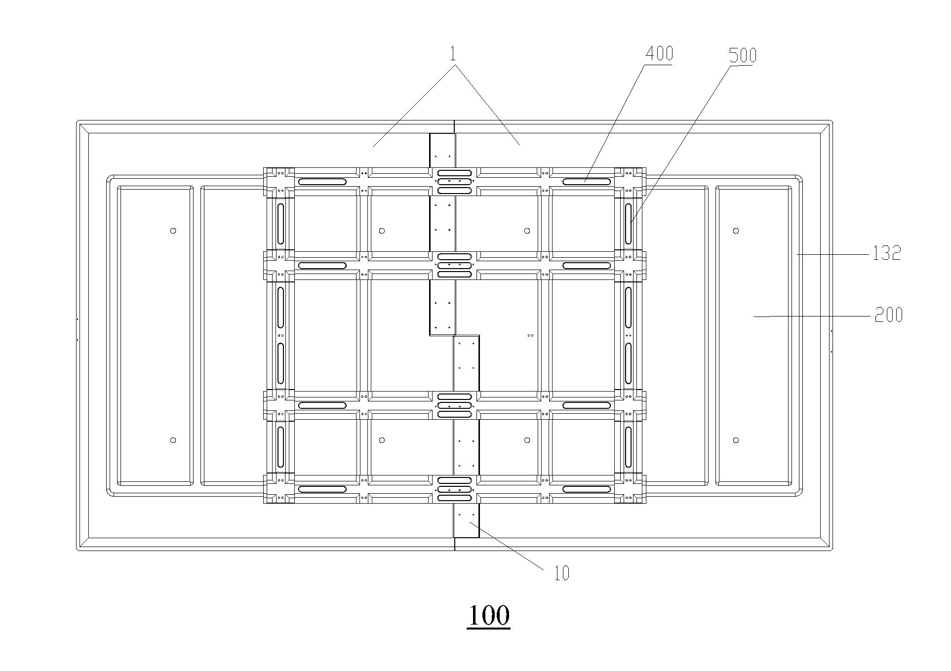
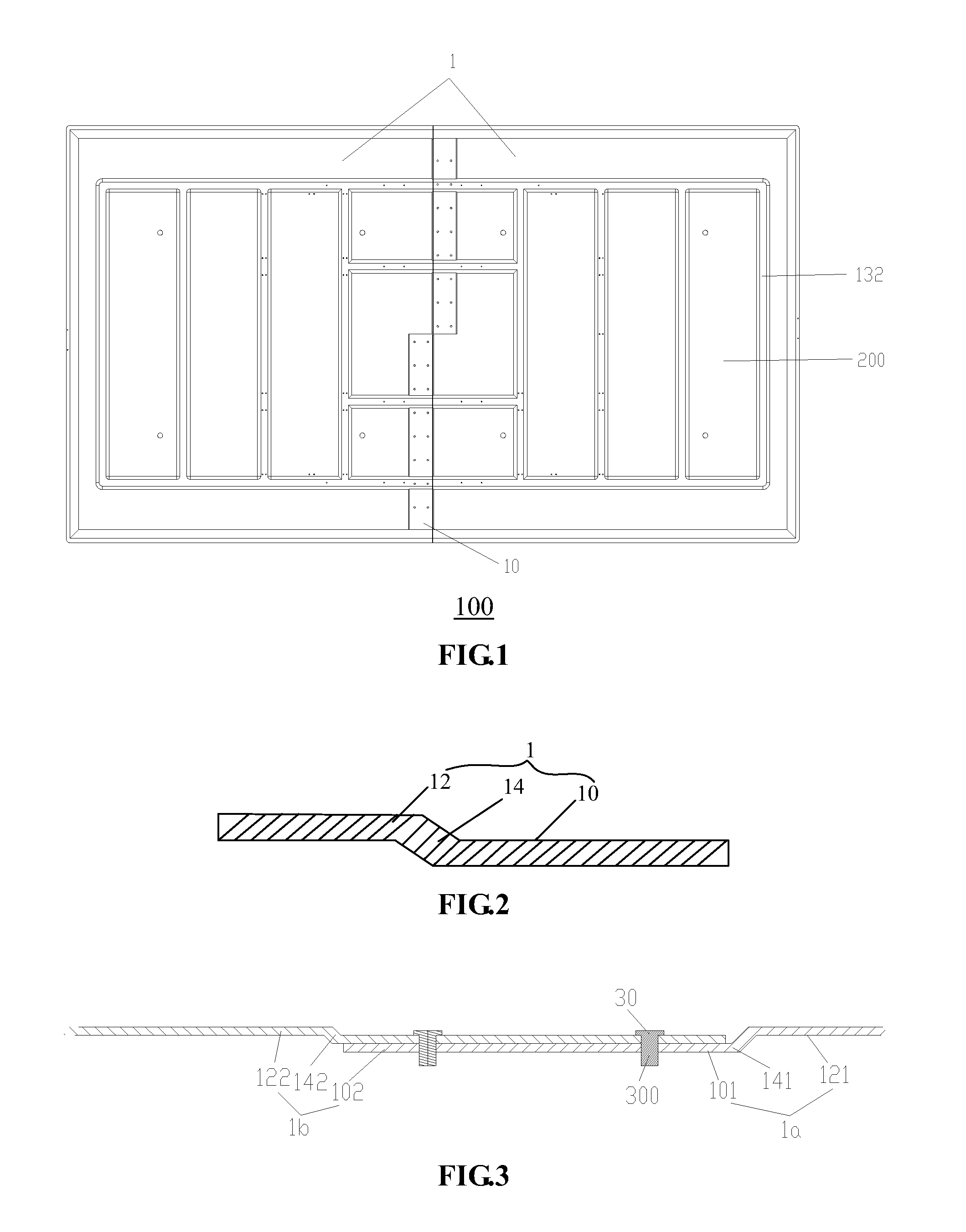
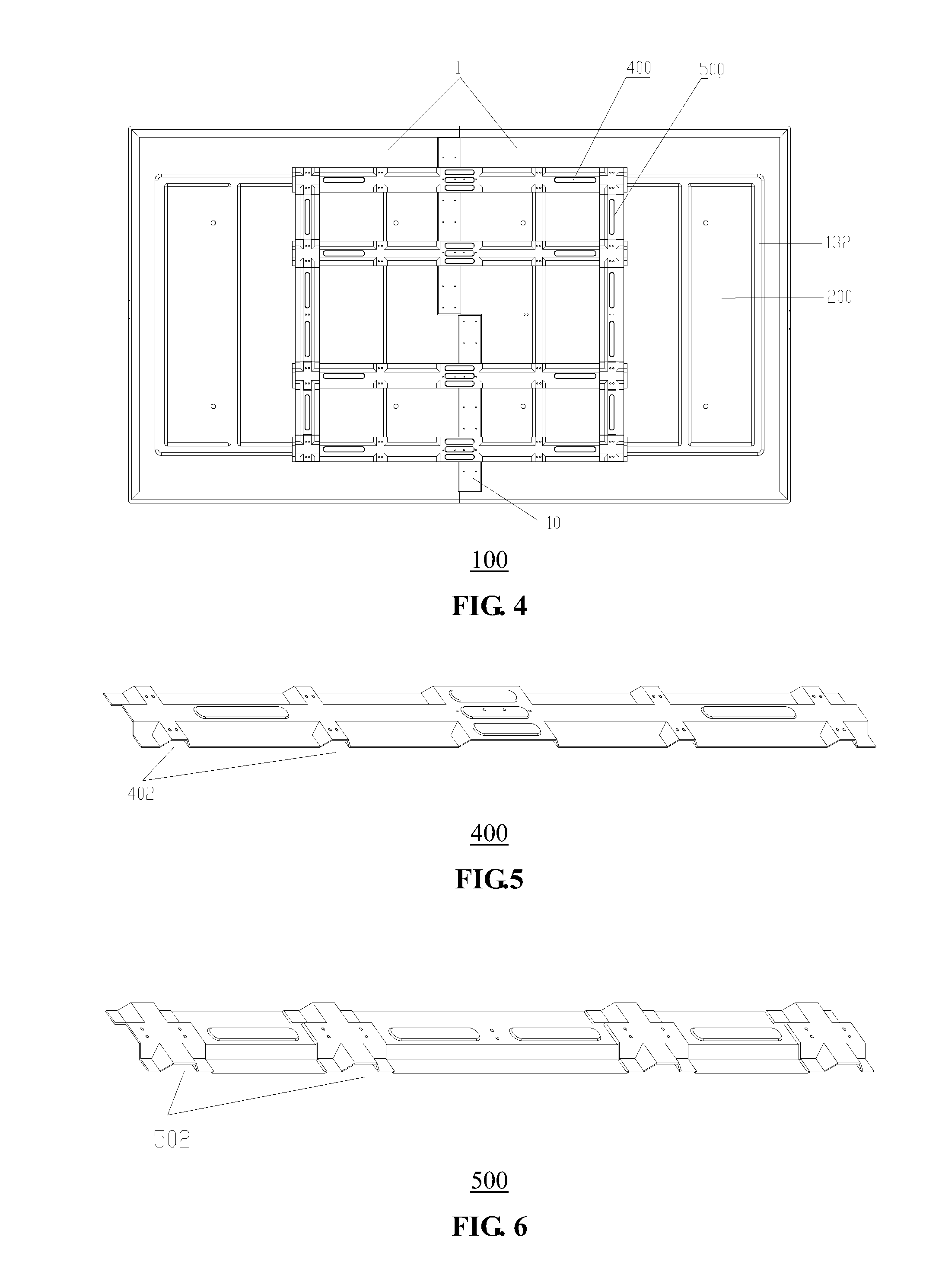
[0018]As illustrated in FIGS. 1 and 2, the invention provides a splicing backplane 100 for a backlight module, which is arranged on the backside of the backlight module 200. The splicing backplane 100 comprises a mounting portion 10 and a supporting portion 12, wherein the horizontal height of the mounting portion 10 is level with or lower than that of the supporting portion 12; and a plurality of the splicing backplanes 100 are assembled together by the mutual superposition of various mounting portions 10.

[0019]The splicing backplane 100, taken as a supporting mechanism for the large-size backlight module 200, is arranged on the backside of the backlight module 200, formed by the mutual superposition and splicing of a plurality of sets of spliced backplanes 1, and used for supporting the whole backlight module 200 by the extension of a plurality of sets of the spliced backplanes 1. As such, a large-size backplane 1 is not required to be formed to support the backlight module, and t...


PUM

PropertyMeasurementUnit
inclination angleaaaaaaaaaa

Abstract

The invention provides a splicing backplane for a backlight module, which is arranged on the backside of the backlight module. The splicing backplane comprises a mounting portion and a supporting portion, wherein the horizontal height of the mounting portion is level with or lower than that of the supporting portion; and a plurality of the splicing backplanes are assembled together by the mutual superposition of various mounting portions. A plurality of the splicing backplanes are superposed with each other and combined into one, and the height differences between the mounting portions and the supporting portions of two adjacent backplanes are unequal, so that one backplane can be accommodated into the other backplane. In addition, after the superposition, the overall thickness of the backplanes is invariable.

Description

FIELD OF THE INVENTION[0001]The invention relates to a backlight module, in particular to a splicing backplane applicable for supporting the backlight module.BACKGROUND OF THE INVENTION[0002]With the development of LCD technology, the production of large-size liquid-crystal-display televisions (LCD TV) and modules has become a trend. In large-size backlight modules, due to the relatively large size, backlight backplanes are hard to be subjected to one-step punch forming, so that two or more sets of moulds are usually adopted for the punch forming of a plurality of accessories to complete assembly. In addition, due to the relatively large weight of the large-size LCD modules, the splicing mode of the backplanes is particularly important and directly affects the reliability and the economy of the backplanes.[0003]Therefore, it's necessary to provide a splicing backplane for a backlight module, having the advantages of simple structure, easy assembly and steady support.SUMMARY OF THE I...

Claims


Application Information

Patent Timeline
Patent Type & Authority Applications(United States)
IPC IPC(8): G02F1/1333
CPCG02F1/133308G02F2001/133328G02F2001/133314G02F1/133314G02F1/133328
Inventor KUO, YI CHENGHSIAO, YUCHUNZHANG, YANXUE
Owner TCL CHINA STAR OPTOELECTRONICS TECH CO LTD
Why Eureka
Try Eureka