Imaging device
- Summary
- Abstract
- Description
- Claims
- Application Information
AI Technical Summary
Benefits of technology
Problems solved by technology
Method used
Image
Examples
first embodiment
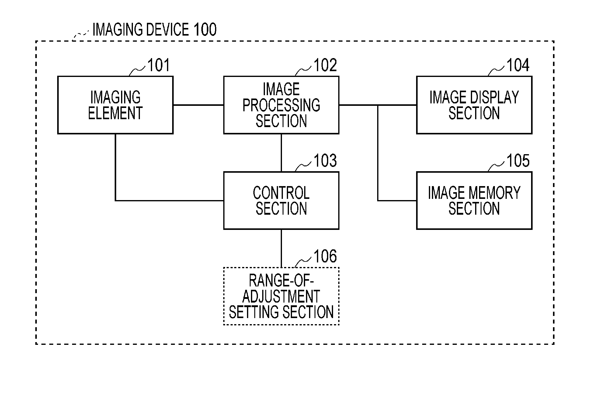
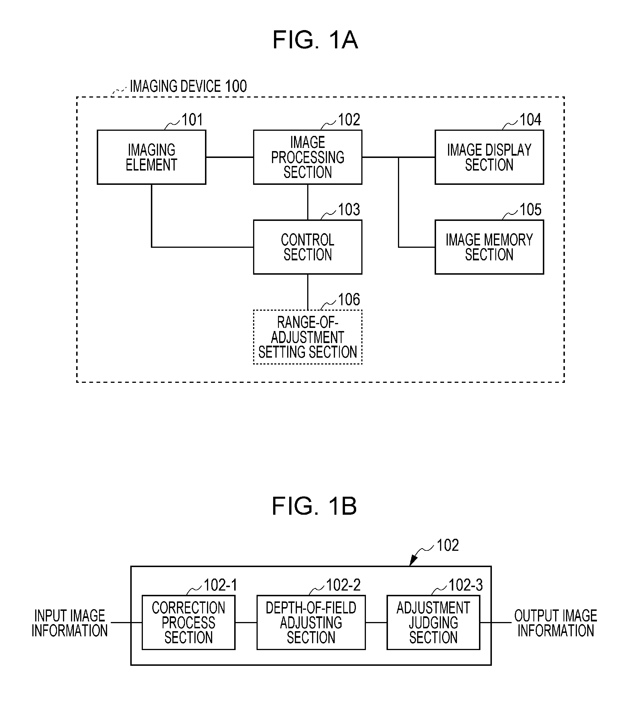
[0026]FIG. 1A is a functional block diagram showing an example configuration of an imaging device according to an embodiment of the present invention. An imaging device 100 according to the present embodiment includes an imaging element 101, an image processing section 102, a control section 103, an image display section 104, and an image memory section 105. A range-of-adjustment setting section 106, which can be optionally provided, will be described in section “Second Embodiment”.
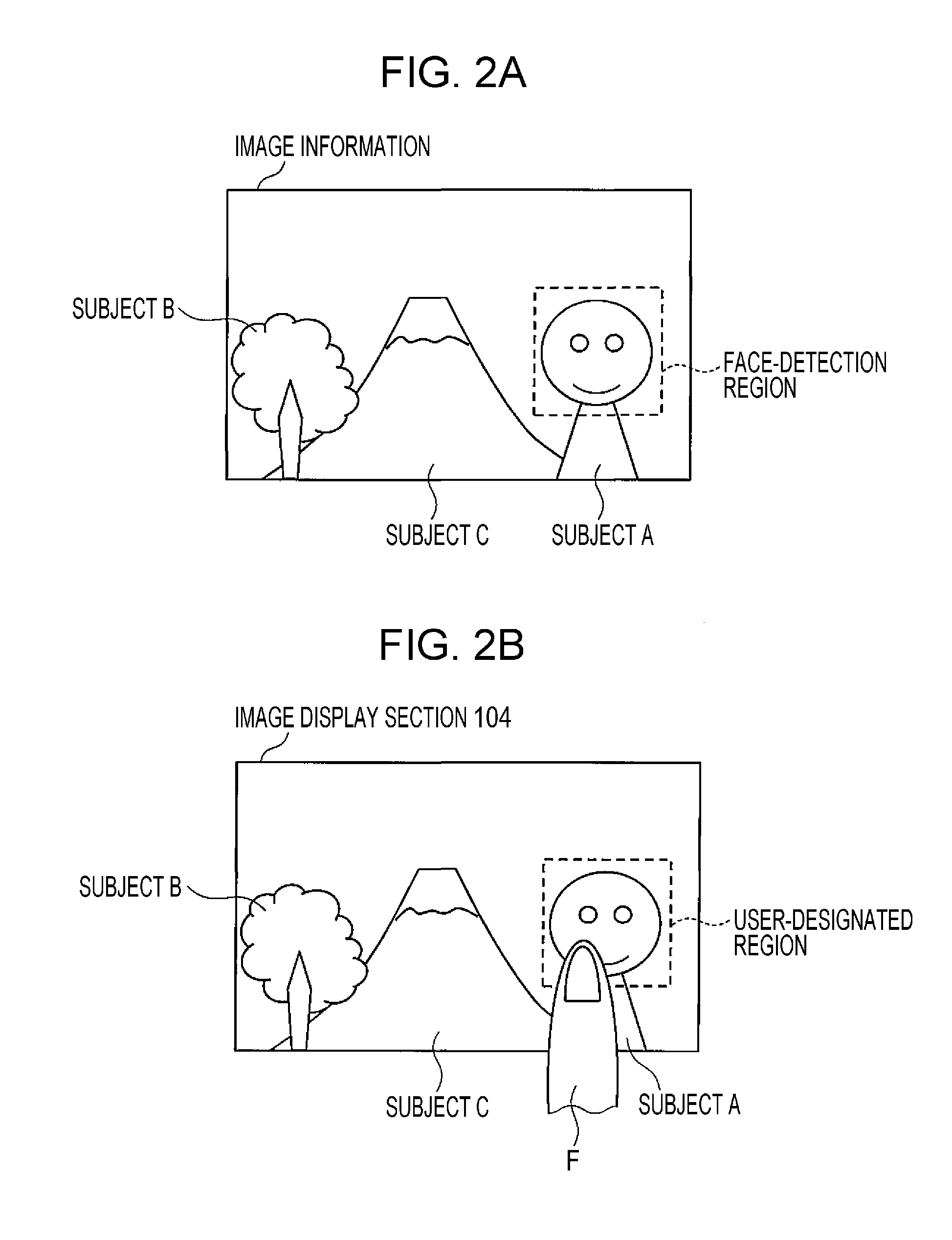
[0027]The imaging element 101 obtains image information. The imaging element 101 includes a solid-state imaging element, a lens, and the like. Examples of the solid-state imaging element include a CCD (charge-coupled device) and a CMOS (complementary metal oxide semiconductor) sensor. Further, the imaging element 101 includes a component or mechanism for a focus adjustment. Such a component or mechanism is achieved for example by driving a lens with an actuator or driving a liquid lens. Making a focus pos...
second embodiment
[0059]Next, a second embodiment is described.
[0060]Since an example configuration of an imaging device 100 according to the present embodiment is the same as that of the first embodiment, a detailed description of each of the common components is omitted.
[0061]The imaging device 100 according to the present embodiment allows the user to set a range over which a depth-of-field extension is made. For example, the imaging device 100 according to the present embodiment includes the range-of-adjustment setting section 106 shown in FIG. 1A. For example, the image display section 104 displays such a screen as that shown in FIG. 6, and the range-of-adjustment setting section 106 allows the user to set the depth of field. FIG. 6 shows a case where the image display section 104 is constituted by a touch panel and the user makes a depth correction level adjustment with the finger F. The present embodiment sets discrete depth correction levels of 0 to 3. At the depth correction level of 0, no d...
third embodiment
[0069]The first and second embodiments described above have dealt with only cases where the depth of field is extended. However, as in the case of a third embodiment of the present invention, it is possible to incorporate image processing directed to a depth-of-field reduction. As shown in FIG. 9, a scale of depth correction level adjustment is set so that a depth-of-field extension is made on a positive side with respect to a reference and a depth-of-field reduction is made on a positive side with respect to the reference. In the case of a depth correction level set at the reference or on the positive side with respect to the reference, a process similar to the method described above is performed.
[0070]In the case of a depth correction level set on the negative side with respect to the reference, the depth of field is reduced. In this case, too, as in the case of an extension, focusing is set on a main subject before photo shooting, and during the photo shooting, image information ...
PUM
 Abstract
Description
Claims
Application Information
 - R&D
- Intellectual Property
- Life Sciences
- Materials
- Tech Scout
- Unparalleled Data Quality
- Higher Quality Content
- 60% Fewer Hallucinations
Browse by: Latest US Patents, China's latest patents, Technical Efficacy Thesaurus, Application Domain, Technology Topic, Popular Technical Reports.
© 2025 PatSnap. All rights reserved.Legal|Privacy policy|Modern Slavery Act Transparency Statement|Sitemap|About US| Contact US: help@patsnap.com


