Formed material manufacturing method

a manufacturing method and material technology, applied in the field of formed material manufacturing methods, can solve the problems of difficult change, inability to increase the thickness of the body to the level of the mold clearance, and practically impossible to control the thickness increase during the operation, so as to reduce the weight and material cost of the formed material, avoid unnecessary increases in the thickness of the flange and the top wall, and reduce the circumferential wall of the body. the effect of thickness reduction

Active Publication Date: 2016-05-26
NISSHIN STEEL CO LTD
View PDF3 Cites 7 Cited by
  • Summary
  • Abstract
  • Description
  • Claims
  • Application Information

AI Technical Summary

Benefits of technology

[0016]With the formed material manufacturing method in accordance with the present invention, the body is formed by drawing the body preform while applying the compressive force along the depth direction of the body preform to the body preform. As a result, thickness reduction of the circumferential wall of the body caused by the drawing process can be avoided, and the necessary thickness of the circumferential wall can be ensured even by using a blank metal sheet which is thinner than that in conventional methods. Further, since at least one compression drawing is performed such as to be completed before the pad portion reaches bottom dead center, and the adjustable support force of the support portion acts as the compressive force upon the body preform when the body preform is drawn, even when the processing conditions are changed or the thickness of the blank metal sheet is changed, the process can be flexibly adapted to those changes. As a result, unnecessary increases in the thickness of the flange and the top wall can be avoided, the process can be flexibly adapted to changes in the processing conditions or thickness of the blank metal sheet, and the formed material can be efficiently reduced in weight and material cost.

Problems solved by technology

Thus, with the conventional compression drawing method implemented in the bottomed state, the thickness cannot be increased to that equal to the mold clearance.
Furthermore, where the above-described conditions contributing to the increase in thickness have once been determined, they are difficult to change.
Therefore, it is practically impossible to control the degree of thickness increase during the operation.

Method used


Image

  • Formed material manufacturing method
  • Formed material manufacturing method
  • Formed material manufacturing method

Examples


embodiment 1

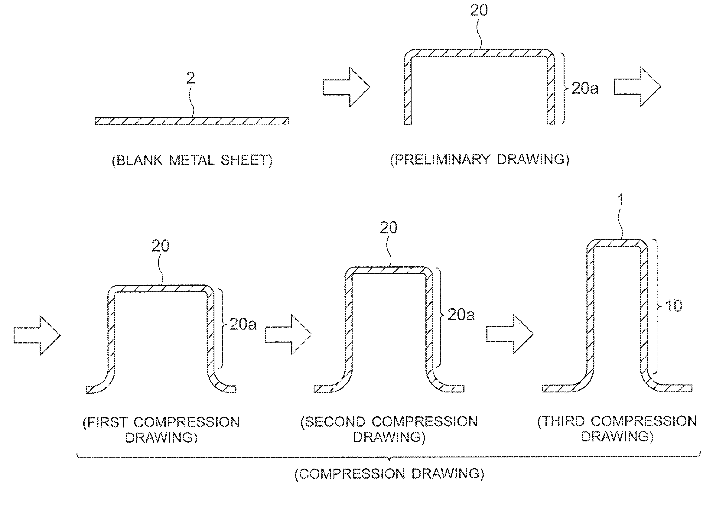
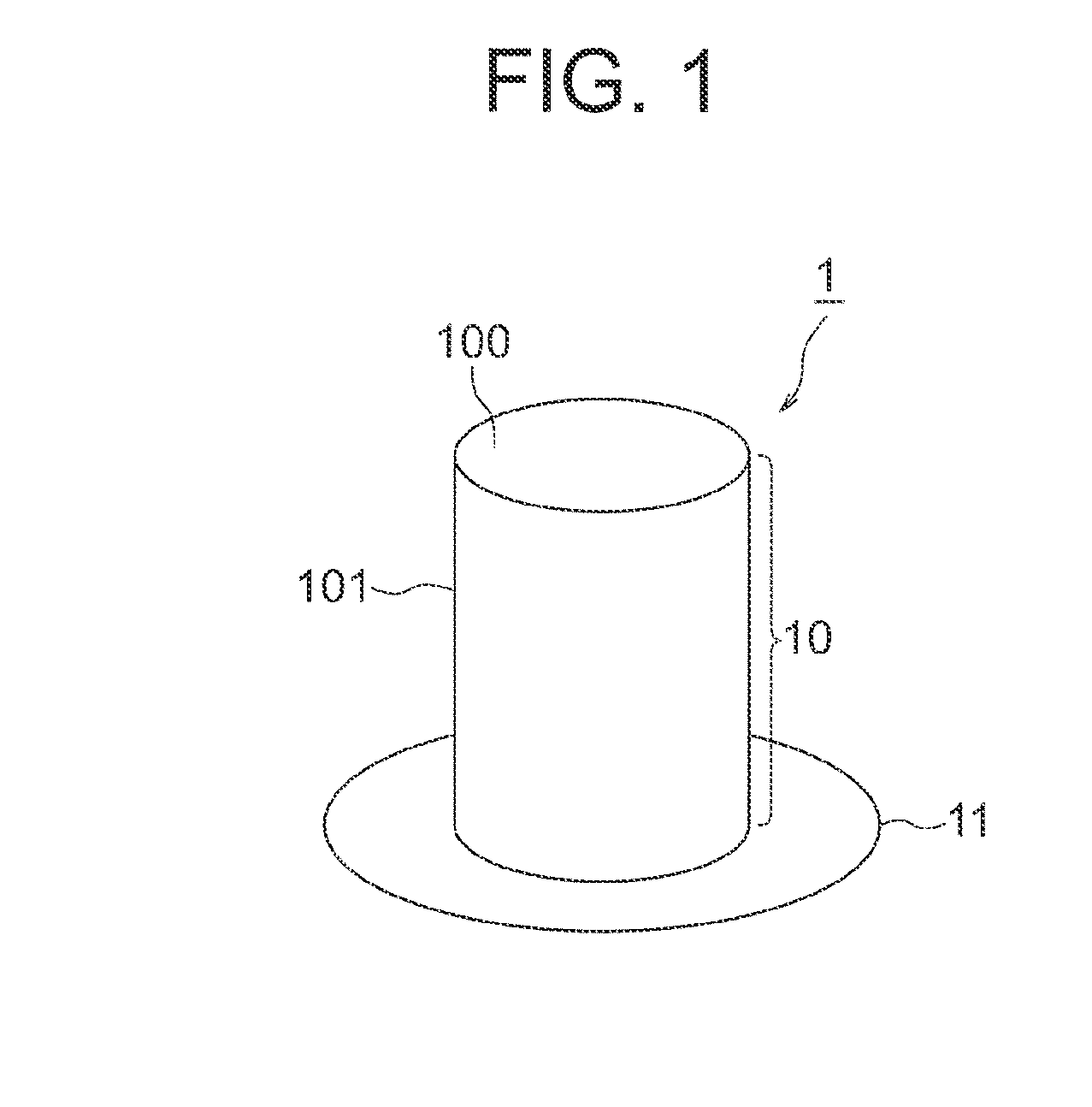
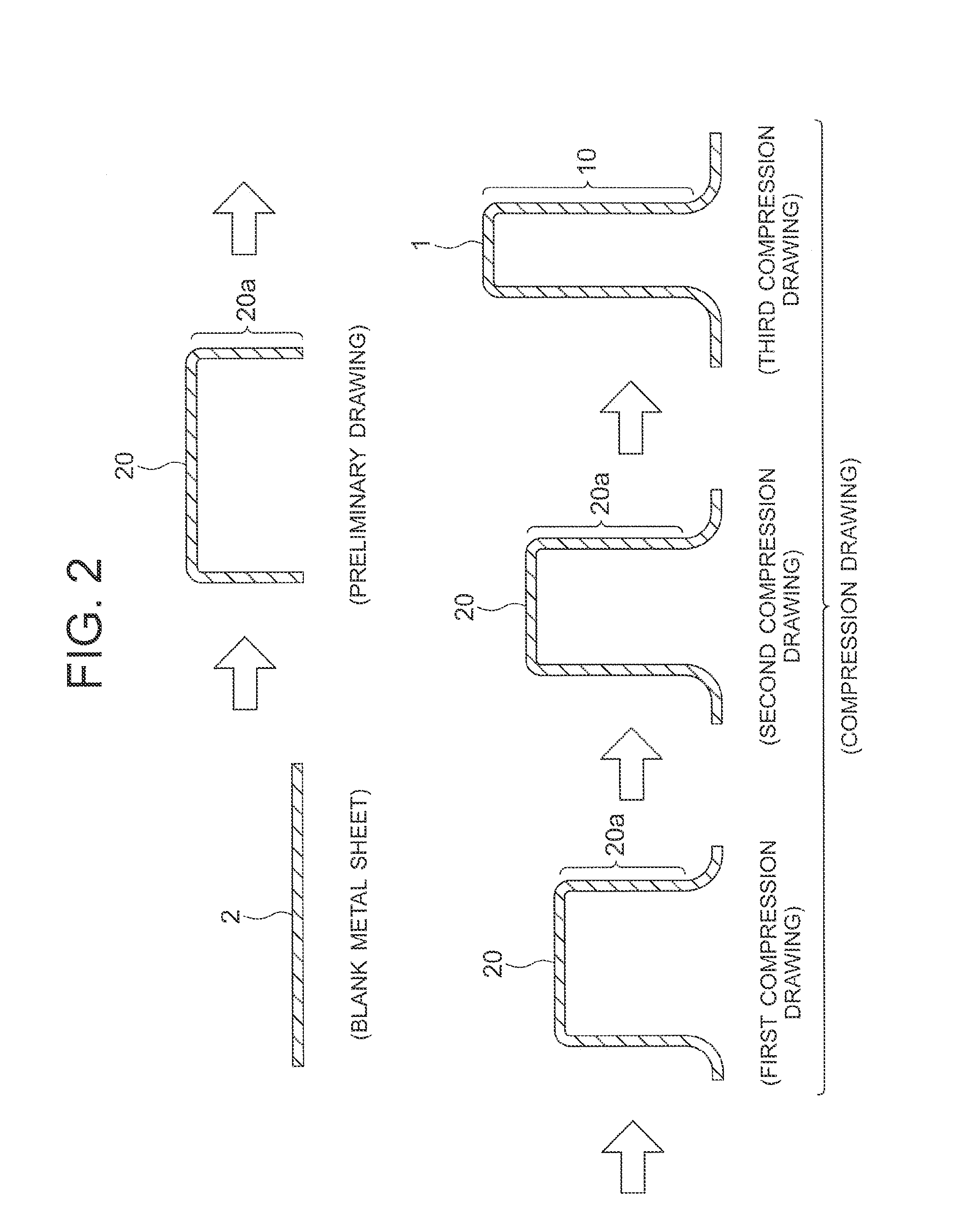
[0029]FIG. 1 is a perspective view of the formed material 1 manufactured by the formed material manufacturing method according to Embodiment 1 of the present invention. As depicted in FIG. 1, the formed material 1 manufactured by the formed material manufacturing method of the present embodiment has a body 10 and a flange 11. The body 10 is a tubular part having a top wall 100 and a circumferential wall 101 extending from the outer edge of the top wall 100. Depending on the targeted use of the formed material 1, the top wall 100 can also be referred to as a bottom wall or the like. In FIG. 1, the body 10 is depicted as having a round cross section, but the body 10 may also have another cross-sectional shape, for example, an elliptical or angular cross section. The top wall 100 can also be further processed, for example, to form a projection further protruding from the top wall 100. The flange 11 is a plate-shaped portion formed at the end of the body 10 (end of the circumferential w...


PUM

PropertyMeasurementUnit
diameteraaaaaaaaaa
thicknessaaaaaaaaaa
thicknessaaaaaaaaaa

Abstract

A formed material having a tubular body and a flange formed at an end of the body is manufactured by multistage drawing of a blank metal sheet. The multistage drawing includes preliminary drawing in which a preliminary body having a body preform is formed from the blank metal sheet, and at least one compression drawing which is performed after the preliminary drawing and in which the body is formed by drawing the body preform while applying a compressive force to the body preform. The at least one compression drawing is performed so as to be completed before the pad portion of pressurization means reaches bottom dead center, and a support force supporting the pad portion acts as the compressive force upon the body preform when the body preform is drawn.

Description

TECHNICAL FIELD[0001]The present invention relates to a formed material manufacturing method for manufacturing a formed material having a tubular body and a flange formed at the end of the body.BACKGROUND ART[0002]As disclosed, for example, in Non-Patent Document 1 and so on, a formed material having a tubular body and a flange portion formed on an end portion of the body is manufactured by performing a drawing process. Since the body is formed by stretching a blank metal sheet in the drawing process, the thickness of the circumferential wall of the body is usually less than that of the blank sheet. On the other hand, since the region of the metal sheet corresponding to the flange shrinks as a whole in response to the formation of the body, the flange thickness is larger than that of the blank sheet.[0003]The abovementioned formed material can be used as the motor case disclosed, for example, in Patent Document 1 and so on. In this case, the circumferential wall of the body is expec...

Claims


Application Information

Patent Timeline
Patent Type & Authority Applications(United States)
IPC IPC(8): B21D24/00B21D22/28
CPCB21D22/28B21D24/00B21D22/26B21D22/30
Inventor NAKAMURA, NAOFUMIYAMAMOTO, YUDAINISHIO, KATSUHIDE
Owner NISSHIN STEEL CO LTD
Why Eureka
Try Eureka