

Maintenance unit and liquid ejecting apparatus
a maintenance unit and liquid ejector technology, applied in the direction of printing, other printing apparatus, etc., can solve the problems of maintenance units, time and effort, and inability to obtain information written in storage elements
- Summary
- Abstract
- Description
- Claims
- Application Information
AI Technical Summary
Benefits of technology
Problems solved by technology
Method used
Image

Examples
Embodiment Construction
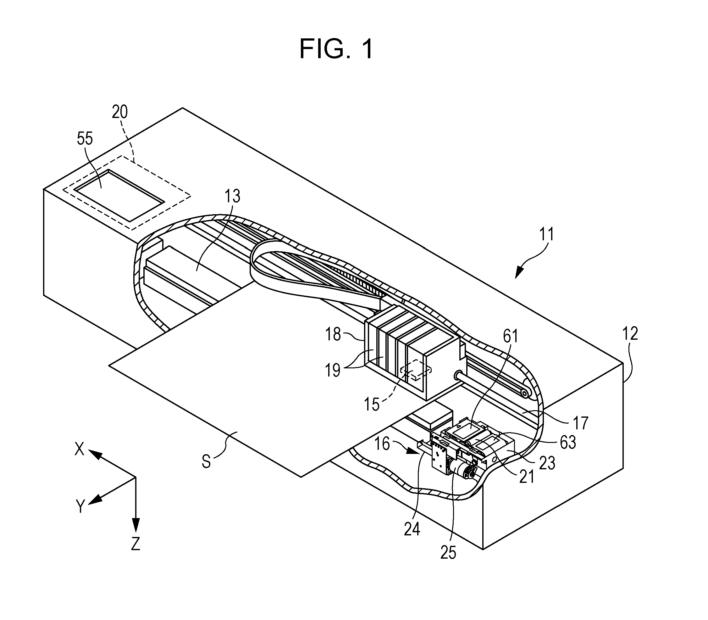
[0036]Hereinafter, a description will be given of an embodiment of a maintenance unit and a liquid ejecting apparatus with reference to drawings. The liquid ejecting apparatus is, for example, an ink jet printer that performs recording (printing) by ejecting ink, which is an example of liquid, to a medium such as a sheet.
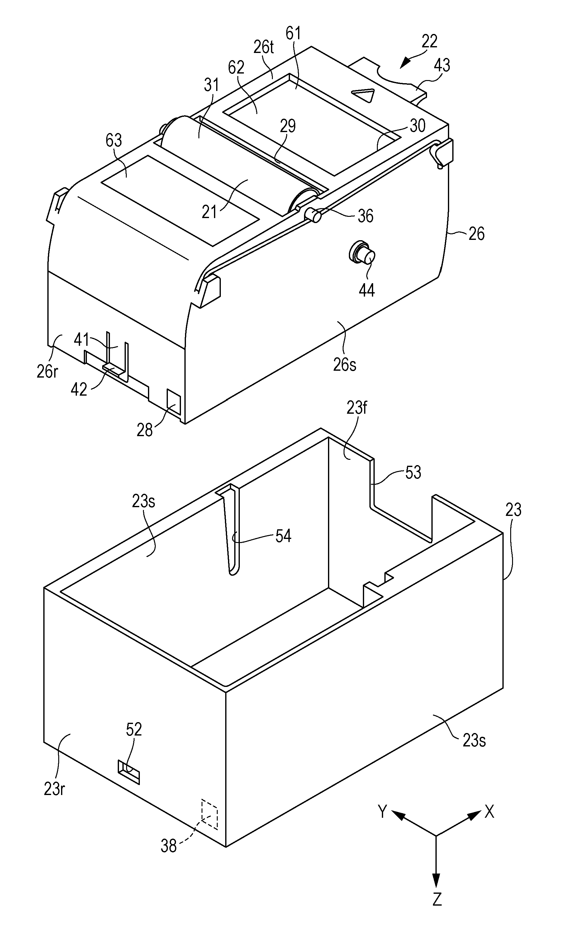
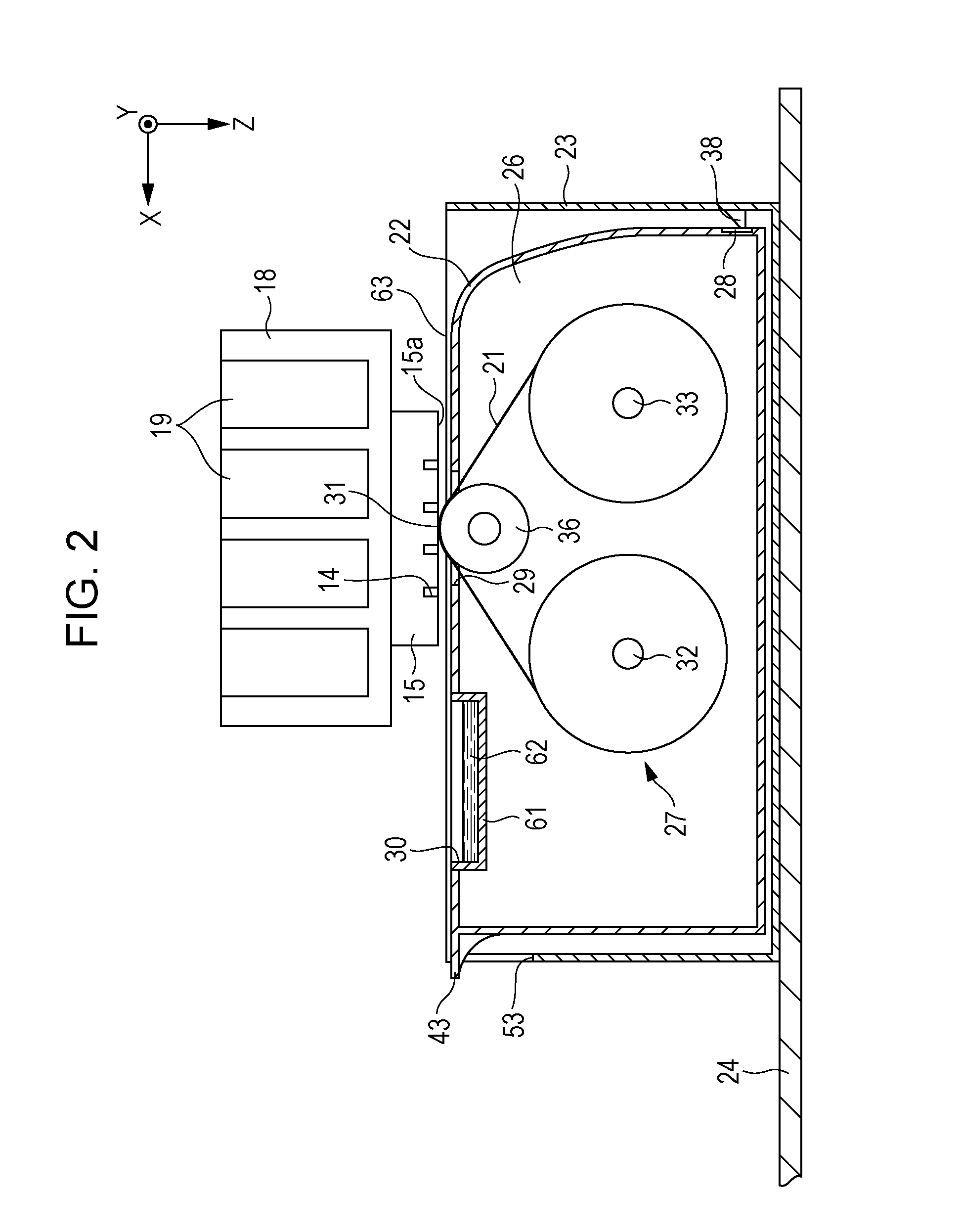
[0037]As illustrated in FIG. 1, a liquid ejecting apparatus 11 includes a case body 12, a medium support section 13 that supports a medium S in the case body 12, a liquid ejecting section 15 that includes nozzles 14 (see FIG. 2) capable of ejecting liquid to the medium S that is supported by the medium support section 13, and a maintenance device 16 that is for performing maintenance of the liquid ejecting section 15. In addition, a display section 55 such as a liquid crystal monitor is provided on an outer surface side of the case body 12.
[0038]In addition, the liquid ejecting apparatus 11 is provided with a control section 20 that is arranged at an arbitrary posit...
PUM
 Abstract
Description
Claims
Application Information