Device and method for a rail vehicle

a technology for rail vehicles and testing devices, applied in the direction of mechanically controlled devices, transportation and packaging, brake systems, etc., can solve the problems of large difficulty, high cost, unattractive attachment mechanisms, etc., and achieve the effect of increasing the weight of the payload and increasing the bending stress of the sha

Inactive Publication Date: 2016-05-26
EUREKA NAVIGATION SOLUTIONS
View PDF0 Cites 7 Cited by
  • Summary
  • Abstract
  • Description
  • Claims
  • Application Information

AI Technical Summary

Benefits of technology

[0004]It is an object of the invention to provide devices and methods for rail vehicles, which allow a universal and simple coupling to the rail vehicle with optimum procedure of an attached device in operation.
[0089]In summary, some aspects of the present invention allow the attachment of components to a rail vehicle in advantageous manner. Among other things, the invention is based on the realization that the shaft of a rail vehicle can advantageously be used for attaching a device, in particular electronics. The attachment of the device in particular has to be very robust, but offer contact surface with the shaft as small as possible. Hereby, water accumulations are avoided, thereby reducing the corrosion of the shaft. A notch effect on the shaft should absolutely be avoided. Similarly, damage to the varnish should be absent. A band used for attachment can be manufactured from steel. However, then, it is convenient to use a further material such as for example a polymer or the like on the inner side of the steel band, thus the side facing the shaft. It could have a knob profile or else a car tire profile on the side facing the shaft. Hereby, the contact surface is further reduced and the materials are protected. As the attachment material, in particular softer materials than that of the shaft or of the varnish layer on the shaft come into consideration. Knobs and tire profiles also can be used on the side facing the steel band since here too corrosion aspects can be relevant. The attachment of the device to the shaft should be slip-resistant.

Problems solved by technology

In addition, many measuring and testing devices require an access as unimpeded as possible to the or into the rail vehicle and away from the rail vehicle or out of it, for example to transmit data via radio.
Generally, measuring and / or testing devices are therefore attached in an upper outer region of the rail vehicle, however, which is associated with great difficulties due to very different and optionally varying superstructures on the rail vehicle.
Certain possibilities of attachment, for example to the chassis, only come into consideration with additional safety tests, which makes these attachment mechanisms expensive and unattractive.

Method used


Image

  • Device and method for a rail vehicle
  • Device and method for a rail vehicle
  • Device and method for a rail vehicle

Examples


Embodiment Construction

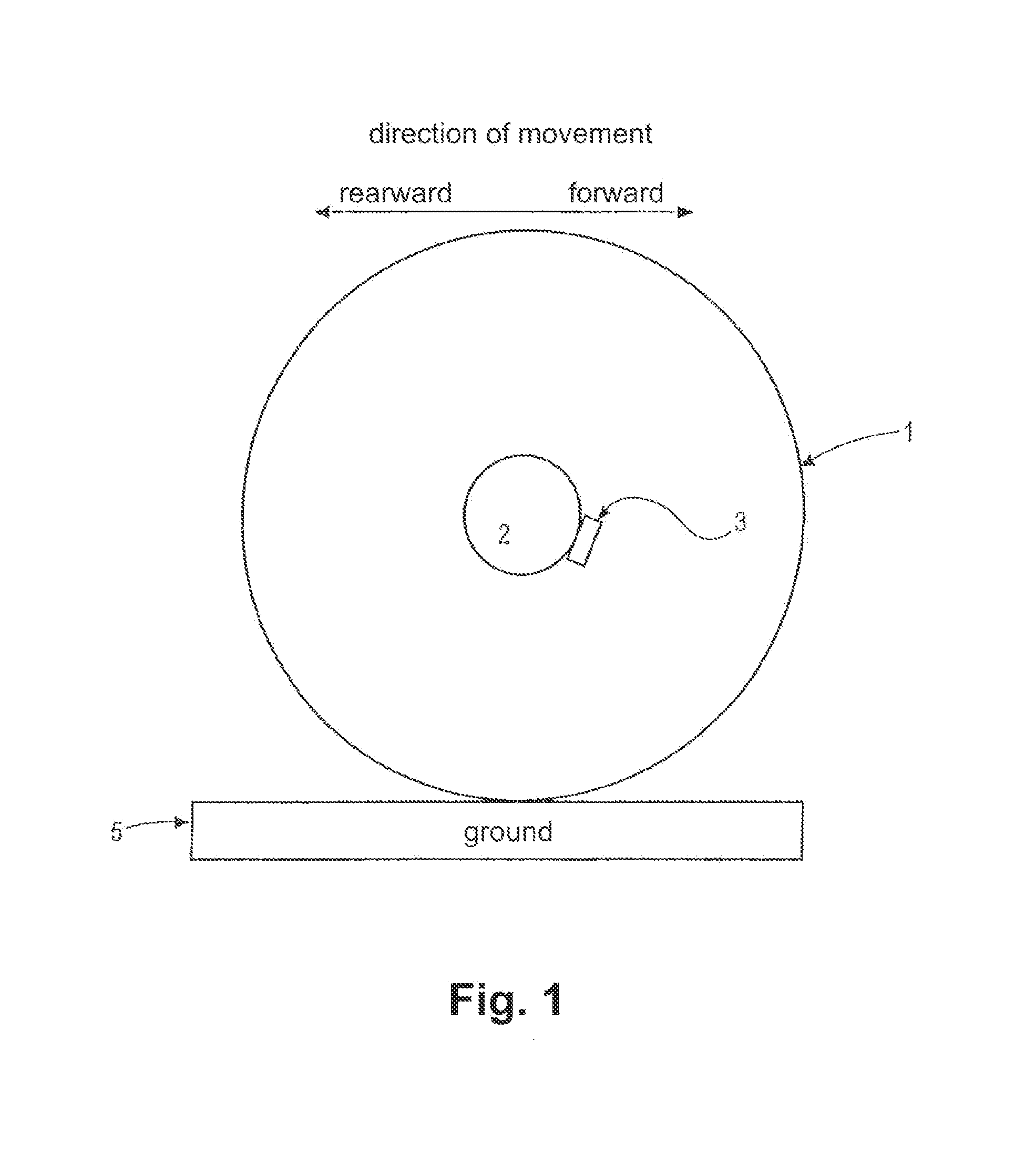
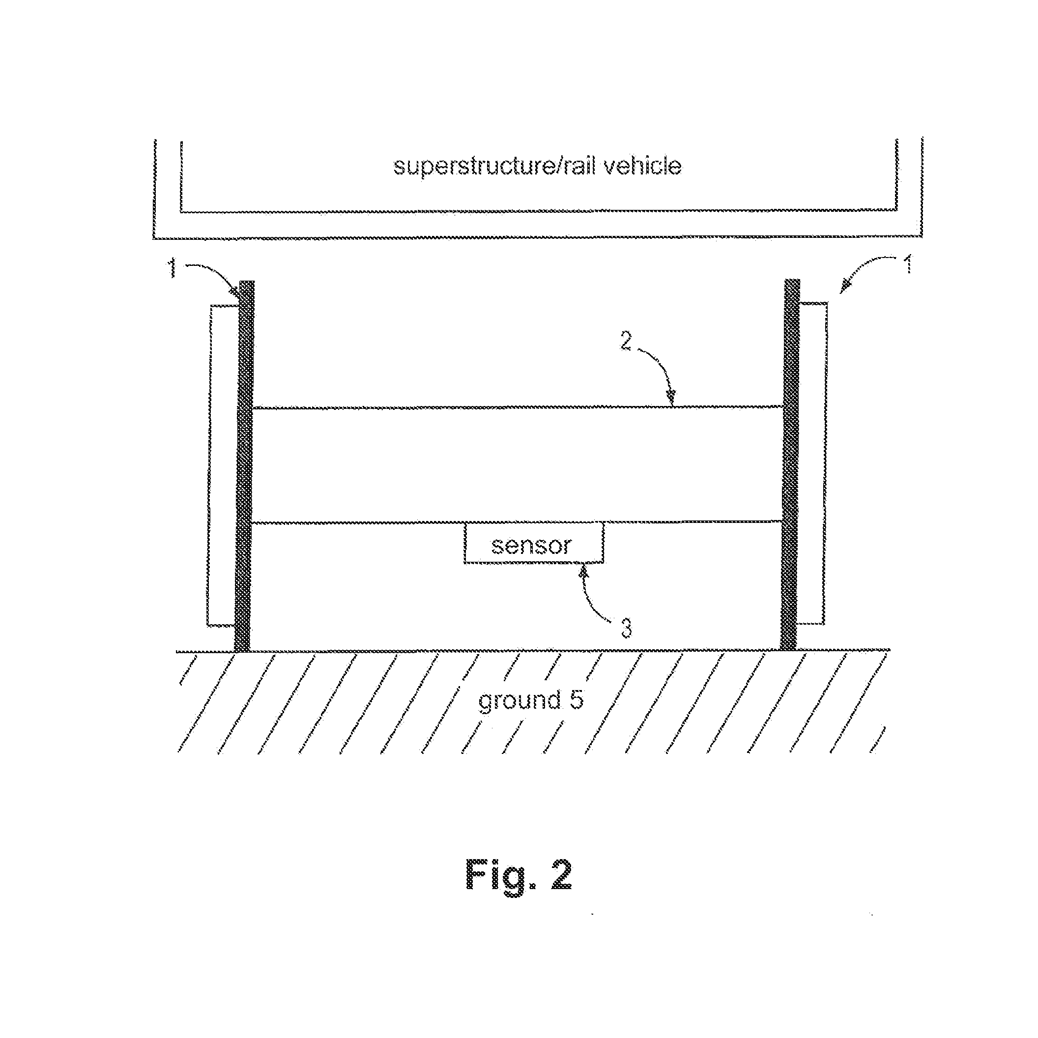
[0118]FIG. 1 shows a simplified representation of a section of an embodiment of a device according to the invention. A wheel 1, for example of a rail vehicle with a superstructure (not shown), is represented. A vehicle axle or the shaft 2 of a vehicle axle (in the context of the present invention often simplifying only referred to as shaft) is attached to the wheel 1, which protrudes into the image plane such that only its cross-sectional area is represented. The shaft 2 can typically connect two similar wheels 1 of the rail vehicle. A device 3 is disposed on the shaft 2, which can be configured according to different aspects of the invention described herein. Quite generally, the device is disposed on the shaft instead of other locations of the rail vehicle. The wheel 1 rolls over the ground 5, which can for example be a rail, upon forward or rearward movement of the rail vehicle. In the device 3, very different sensors, for example a microprocessor, a memory, in particular semicon...


PUM

PropertyMeasurementUnit
frequencyaaaaaaaaaa
frequencyaaaaaaaaaa
frequencyaaaaaaaaaa

Abstract

The invention relates to devices and methods, which relate to the arrangement of a sensor on the shaft of a rail vehicle.

Description

CROSS-REFERENCE TO RELATED APPLICATIONS[0001]This application claims benefit from and is a continuation of U.S. application Ser. No. 13 / 130,147, filed May 19, 2011, entitled DEVICE AND METHOD FOR A RAIL VEHICLE, which claims benefit from and is a U.S. national stage filing under 35 U.S.C. §371 of PCT / EP2009 / 008211 filed on Nov. 18, 2009, entitled DEVICE AND METHOD FOR A RAIL VEHICLE, which claims benefit from German Application Nos. 102009020428.8 filed May 8, 2009, and 1020080057966.1, filed Nov. 19, 2008, entitled DEVICE AND METHOD FOR A RAIL VEHICLE, all of which are hereby incorporated by reference in their entirety.[0002]The present invention relates to devices and methods for measuring and / or testing devices for rail vehicles.SUMMARY OF THE INVENTION[0003]Generally, rail vehicles offer numerous possibilities of attaching measuring or testing devices to them. Almost all of these possibilities require an elaborate adaptation of the attachment mechanisms with different rail vehic...

Claims


Application Information

Patent Timeline
Patent Type & Authority Applications(United States)
IPC IPC(8): B61L25/02
CPCB61L25/028B60T8/1893B60T8/3235B60T8/329B60T17/228B61L15/0081B61L25/021B61L25/026G01P3/22B61L15/0054Y10T29/49826
Inventor LEITEL, HOLGERBEHRENDS, VICTORGENSELEITER, KURTSCHEIBLE, ROLF-STEFAN
Owner EUREKA NAVIGATION SOLUTIONS
Why Eureka
Try Eureka