Method for manufacturing composite material polarizable under the action of a weak electric field

Inactive Publication Date: 2016-05-26
INST NAT DES SCI APPLIQUEES DE LYON
View PDF11 Cites 5 Cited by
  • Summary
  • Abstract
  • Description
  • Claims
  • Application Information

AI Technical Summary

Benefits of technology

[0034]a particular type of plasticizer—namely a phthalate-based plasticizer makes it

Problems solved by technology

The high level of the electric fields to be applied to these polymers constitutes a major obstacle for developing numerous applications, notably for fabricating actuators.
However, the dielectric strengths of su

Method used


Image

  • Method for manufacturing composite material polarizable under the action of a weak electric field
  • Method for manufacturing composite material polarizable under the action of a weak electric field
  • Method for manufacturing composite material polarizable under the action of a weak electric field

Examples


Example

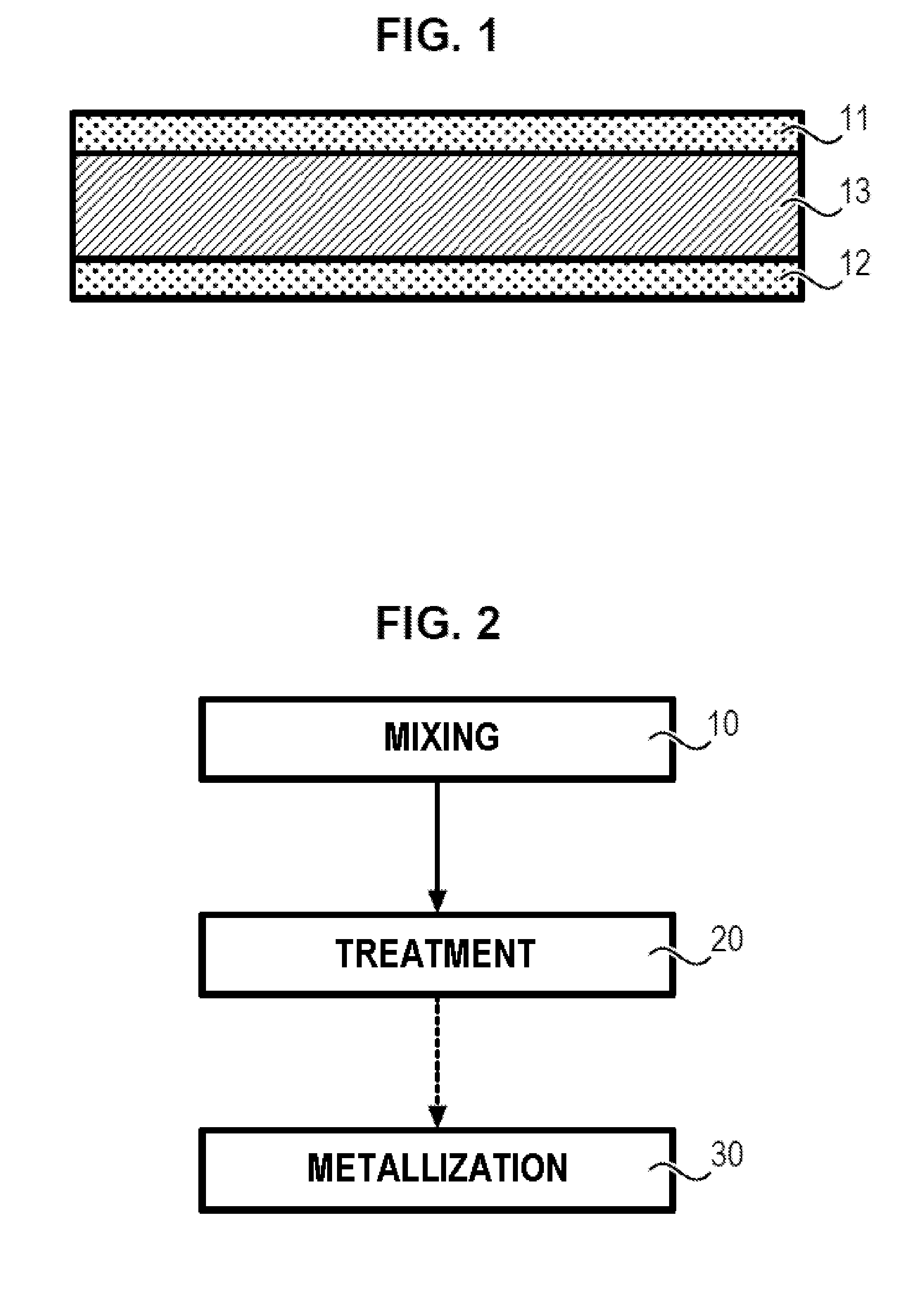
[0064]The composite material and its associated method of manufacture will now be described in more detail, referring to FIGS. 1 and 2.

[0065]Referring to FIG. 1, a composite structure is illustrated. This structure comprises a layer of composite material 13 inserted between two electrically conducting layers 11, 12 forming the electrodes.

[0066]The layer of composite material 13 comprises a mixture of one or more ferroelectric organic polymers with relaxation behavior, and of one or more phthalate-based plasticizers.

[0067]The polymer is for example a P(VDF-TrFE-CFE) terpolymer or a P(VDF-TrFE-CTFE) terpolymer.

[0068]The plasticizer is for example bis(2-ethylhexyl) phthalate (or DEHP, for DiEthylHexyl Phthalate).

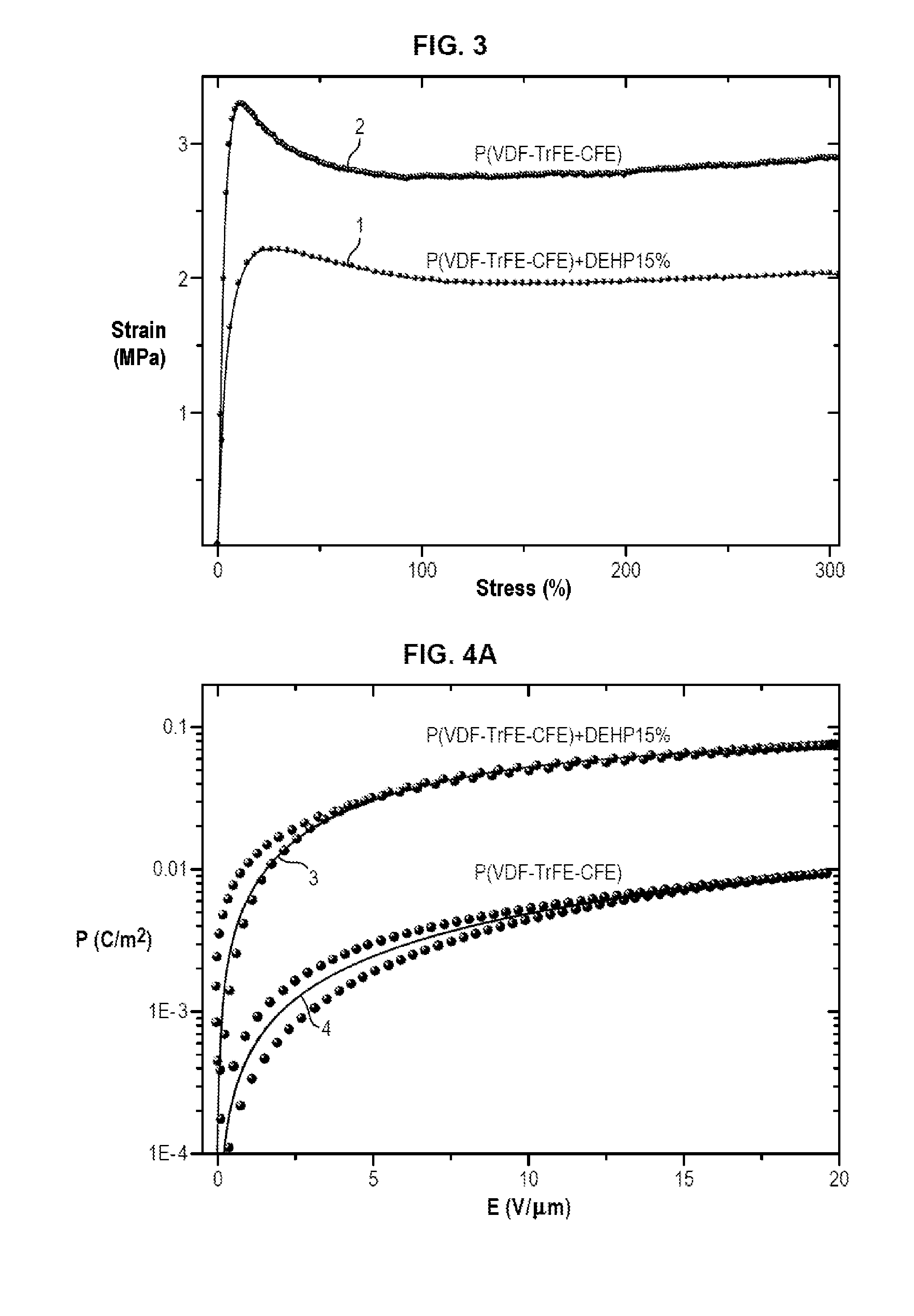
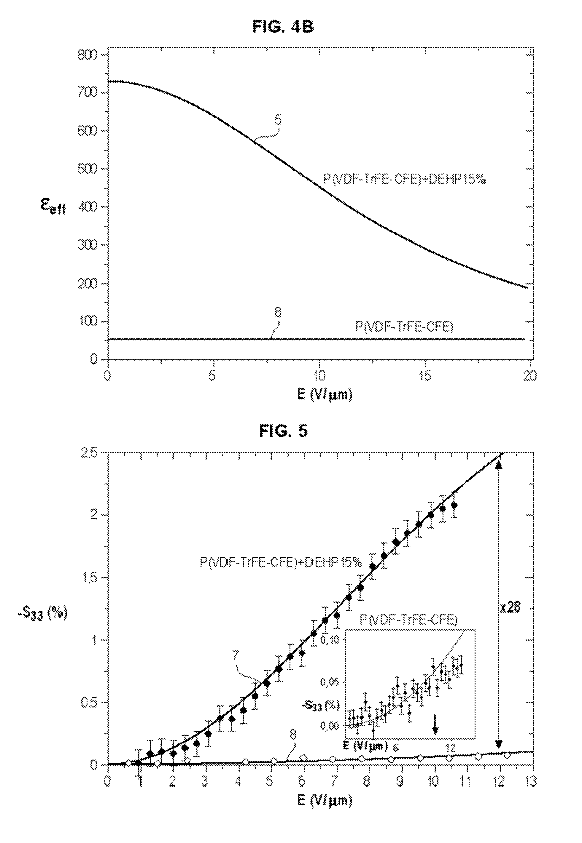
[0069]By mixing a polar phase terpolymer—such as a P(VDF-TrFE-CFE) terpolymer or a P(VDF-TrFE-CTFE) terpolymer—with another material of low polarity—such as a phthalate-based plasticizer—that interacts with the polar phase of the terpolymer, it is possible to increase the diele...


PUM

PropertyMeasurementUnit
Temperatureaaaaaaaaaa
Frequencyaaaaaaaaaa
Temperatureaaaaaaaaaa

Abstract

The present invention relates to a composite (13), characterized in that it comprises:
    • at least one ferroelectric organic polymer with relaxation properties, and
    • at least one phthalate-based plasticizer.

Description

FIELD OF TECHNOLOGY[0001]The present invention relates to the field of technology of composites polarizable under the action of an electric field, and more particularly, composites comprising a ferroelectric organic polymer having relaxation character.[0002]Relaxation character of a polymer means:[0003]that the barrier of transformation between the polar and nonpolar phases of the latter is diffuse and[0004]that at room temperature a reversible change between these phases may be induced under the action of an electric field, with very little hysteresis.[0005]The ferroelectric organic polymers displaying a relaxation character must also possess good mechanical elasticity allowing considerable deformation under the action of an electric field.PRIOR ART[0006]Ferroelectric organic polymers displaying a relaxation character are known, such as terpolymers comprising:[0007]a first monomer of vinylidene fluoride (VDF), combined with[0008]a second monomer selected from trifluoroethylene (TrF...

Claims


Application Information

Patent Timeline
IPC IPC(8): C08K5/12H01L41/193H01L41/09
CPCC08K5/12H01L41/193H01L41/0926C08F214/22C08K5/098H10N30/857C08L27/16C08F214/182H10N30/204
Inventor CAPSAL, JEAN-FABIENGALINEAU, JEREMYCOTTINET, PIERRE-JEANLALLART, MICKAELGUYOMAR, DANIEL
Owner INST NAT DES SCI APPLIQUEES DE LYON
Why Eureka
Try Eureka