Anode layer slit ion source

a technology of anode layer and ion source, applied in the field of ion sources, can solve the problem of unsatisfactory racetrack shape of ion emitting slits

Inactive Publication Date: 2016-05-26
GENERAL PLASMA
View PDF21 Cites 8 Cited by
  • Summary
  • Abstract
  • Description
  • Claims
  • Application Information

AI Technical Summary

Problems solved by technology

While prior art anode layers sources are useful, the racetrack shape of the ion emitting slit is not ideal.

Method used


Image

  • Anode layer slit ion source
  • Anode layer slit ion source
  • Anode layer slit ion source

Examples


Embodiment Construction

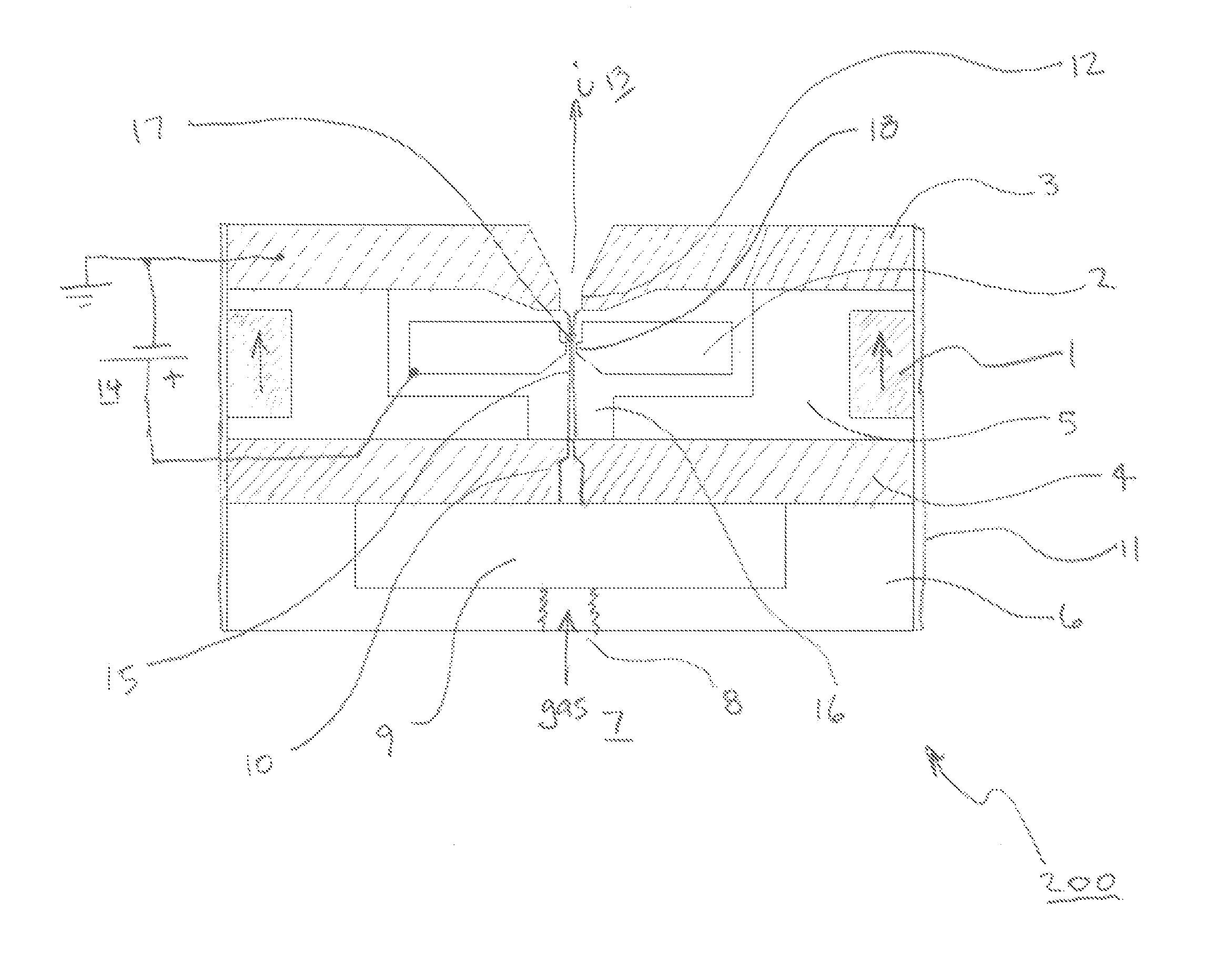
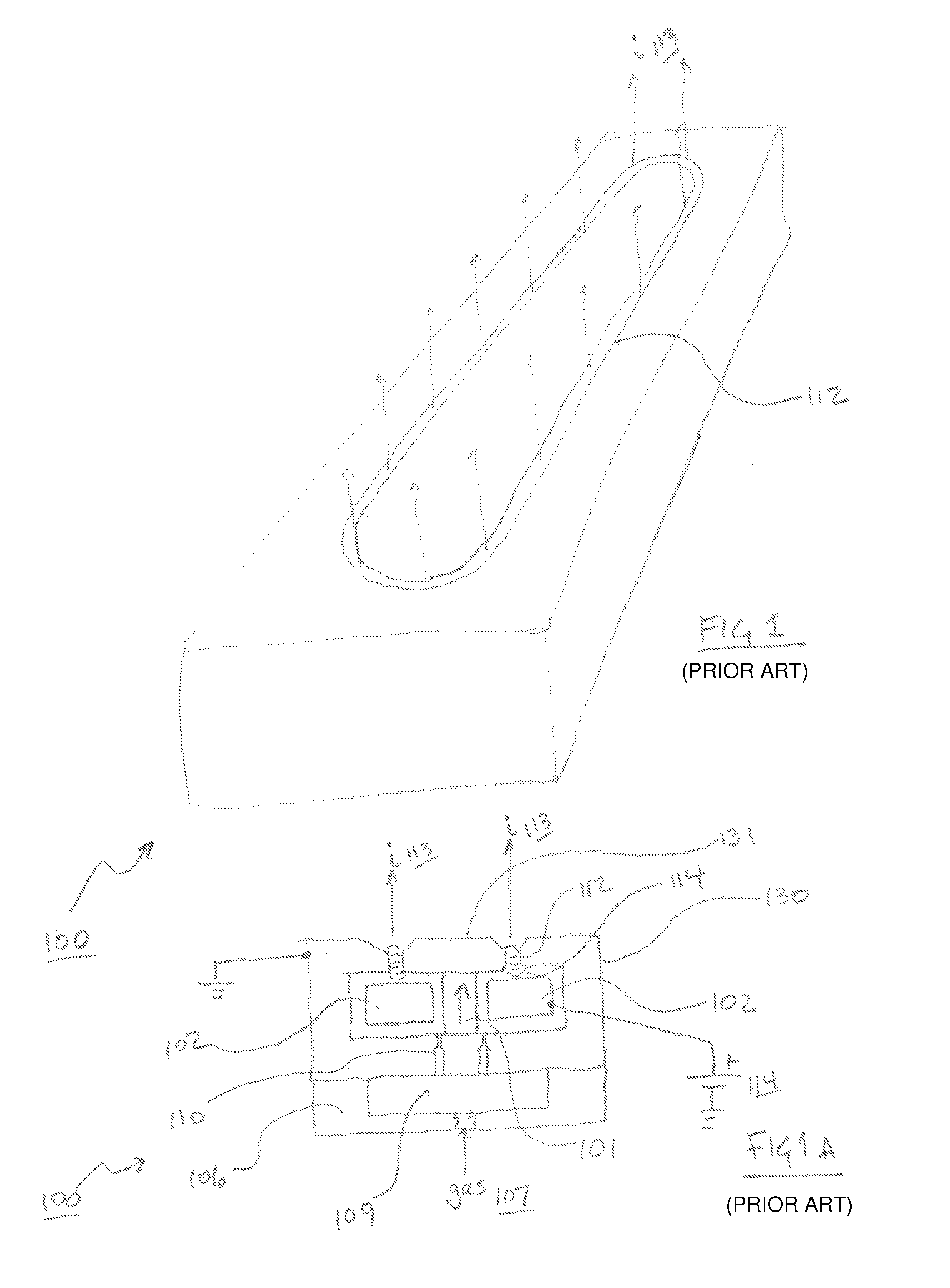
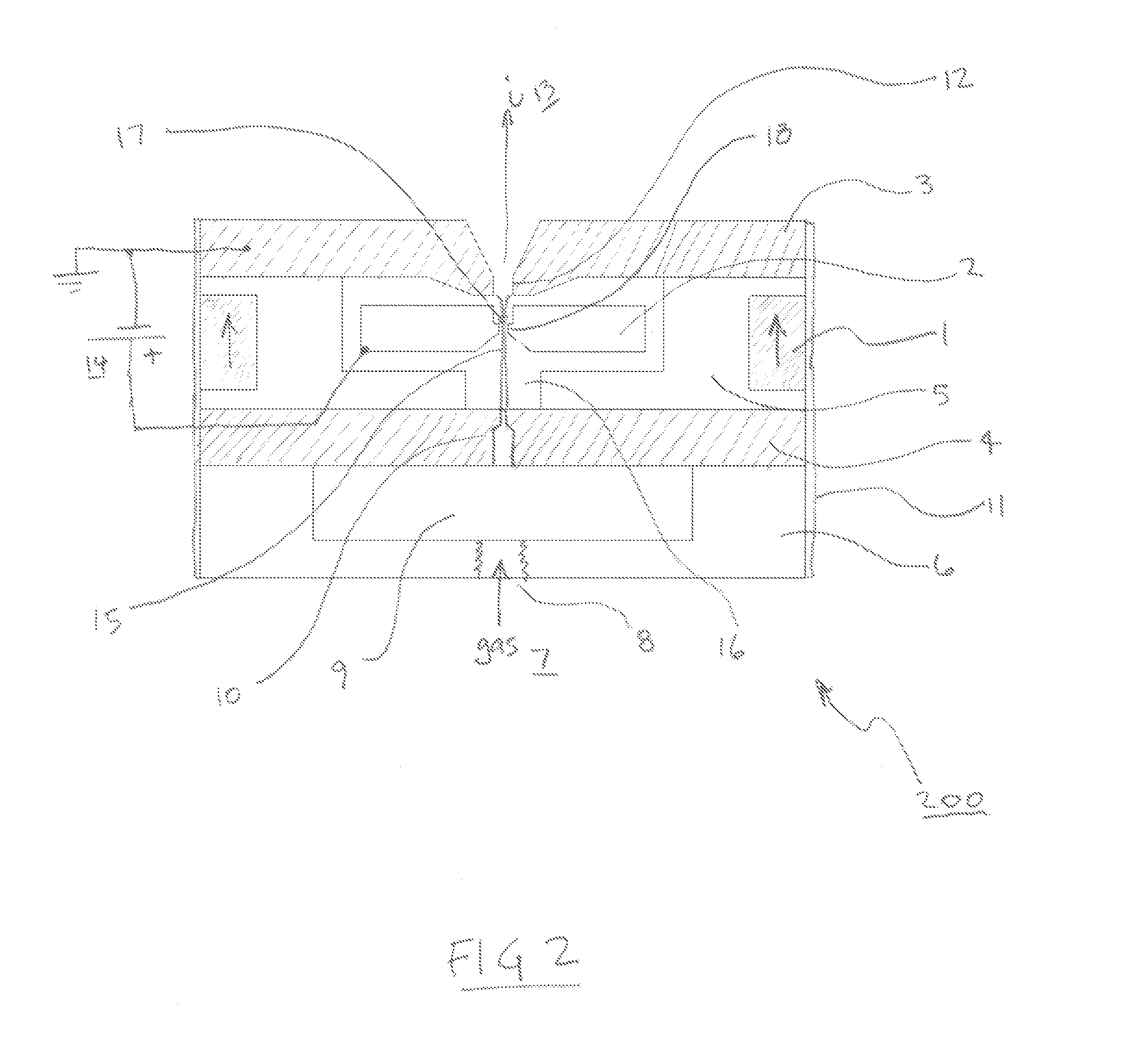
[0015]The present invention has utility as an ion source for industrial applications and space propulsion. All prior art anode layer ion sources have a round or annular racetrack shaped ion dispensing slit. The inventive anode layer slit ion source is termed synonymously a ‘Lineatron’ herein. Within the Lineatron slit, a novel configuration of magnetic and electric fields produces an efficient, closed drift electron containment that creates a uniform linear ion beam over the length of the slit. The result is the Lineatron is an improved anode layer ion source that has several advantages over prior art ion sources.

[0016]It is to be understood that in instances where a range of values are provided that the range is intended to encompass not only the end point values of the range but also intermediate values of the range as explicitly being included within the range and varying by the last significant figure of the range. By way of example, a recited range of from 1 to 4 is intended to...


PUM


Abstract

A linear anode layer ion source is provided that includes a top pole having a linear ion emitting slit. An anode under the top pole has a slit aligned with the top pole ion emitting slit. At least one magnet creates a magnetic field that passes through the anode slit. Wherein the width of the anode slit is 3 mm or less. A process of generating an accelerated ion beam is also provided that includes flowing a gas into proximity to said anode. By energizing a power supply electron flow is induced to the anode and the gas is ionized. Accelerating the ions from the anode through the linear ion emitting slit generates an accelerated ion beam by a process superior to that using a racetrack-shaped slit.

Description

RELATED APPLICATIONS[0001]This application claims priority benefit of U.S. Provisional Application Ser. No. 61 / 834,351 filed Jun. 12, 2013; the contents of which are hereby incorporated by reference.FIELD OF THE INVENTION[0002]The present invention relates in general to ion sources and in particular to ion sources for industrial applications and ion thrusters for space travel.BACKGROUND OF THE INVENTION[0003]The anode layer ion sources are well known having been implemented in industrial applications and ion thrusters for many decades. FIG. 1 shows a 3D view of a prior art anode layer ion source and FIG. 1A shows a section view of this prior art ion source. As shown in FIG. 1, the ion emitting racetrack of an anode layer ion sources can be extended in one axis to have long straight-away sections. In practice, these sources have been made several meters long. This is possible because electrons are confined in an endless closed drift around the racetrack. The closed drift electron con...

Claims


Application Information

Patent Timeline
Patent Type & Authority Applications(United States)
IPC IPC(8): H01J27/14
CPCH01J27/14H01J37/08H01J27/10H01J27/024
Inventor MADOCKS, JOHN E.
Owner GENERAL PLASMA
Why Eureka
Try Eureka