Method of forming a barrier layer of a tunneling magnetoresistive sensor

a tunneling magnetoresistive and sensor technology, applied in the field of tunneling magnetoresistive (tmr) sensors, can solve the problem that tmr sensors cannot be used in practice as submicron-sized read sensors for magnetic recording at high densities, and achieve the effect of preventing electrostatic discharge damage and magnetic and tmr properties

Inactive Publication Date: 2005-01-11
GLOBALFOUNDRIES INC
View PDF20 Cites 126 Cited by
  • Summary
  • Abstract
  • Description
  • Claims
  • Application Information

AI Technical Summary

Benefits of technology

This three-step barrier-layer formation process eliminates oxygen penetration into underlying ferromagnetic layers of the TMR sensor and controls oxygen doping into the barrier layer. As a result, the TMR sensor exhibits magnetic and TMR properties that are better than prior art TMR sensors. In particular, RJAJ is sufficiently low to prevent electrostatic discharge (ESD) damage to a submicron-sized TMR sensor used for magnetic recording at ultrahigh densities.

Problems solved by technology

Unfortunately, such TMR sensors cannot be used in practice as submicron-sized read sensors for magnetic recording at high densities, since RJAJ must be around 4 Ω-μm2 in order to prevent electrostatic discharge (ESD) damage to the sensors.
A smaller δAl—O leads to a desired low RJAJ, but also an undesired low ΔRT / RJ.

Method used


Image

  • Method of forming a barrier layer of a tunneling magnetoresistive sensor
  • Method of forming a barrier layer of a tunneling magnetoresistive sensor
  • Method of forming a barrier layer of a tunneling magnetoresistive sensor

Examples


Embodiment Construction

The following description is the best embodiment presently contemplated for carrying out the present invention. This description is made for the purpose of illustrating the general principles of the present invention and is not meant to limit the inventive concepts claimed herein.

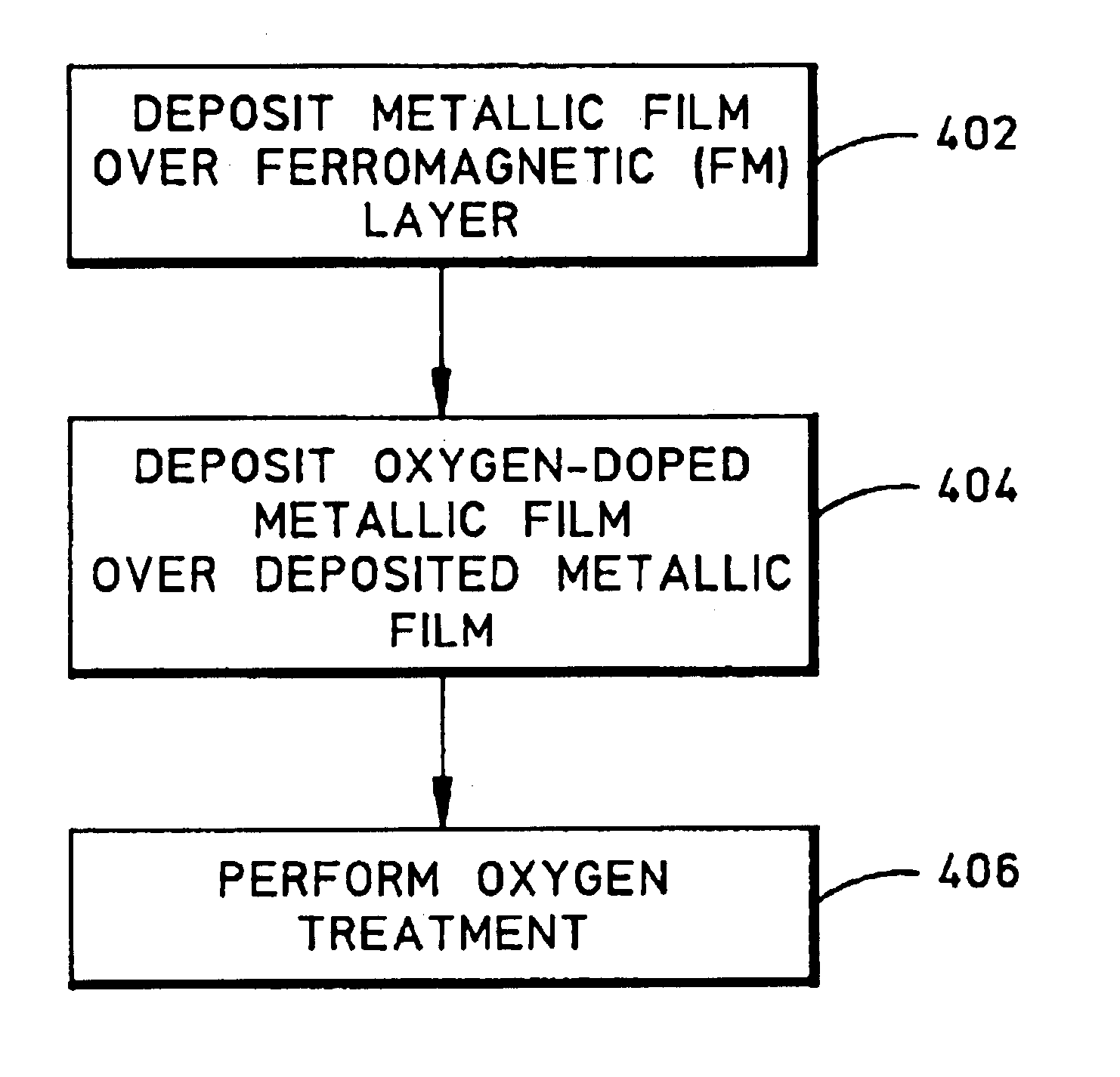
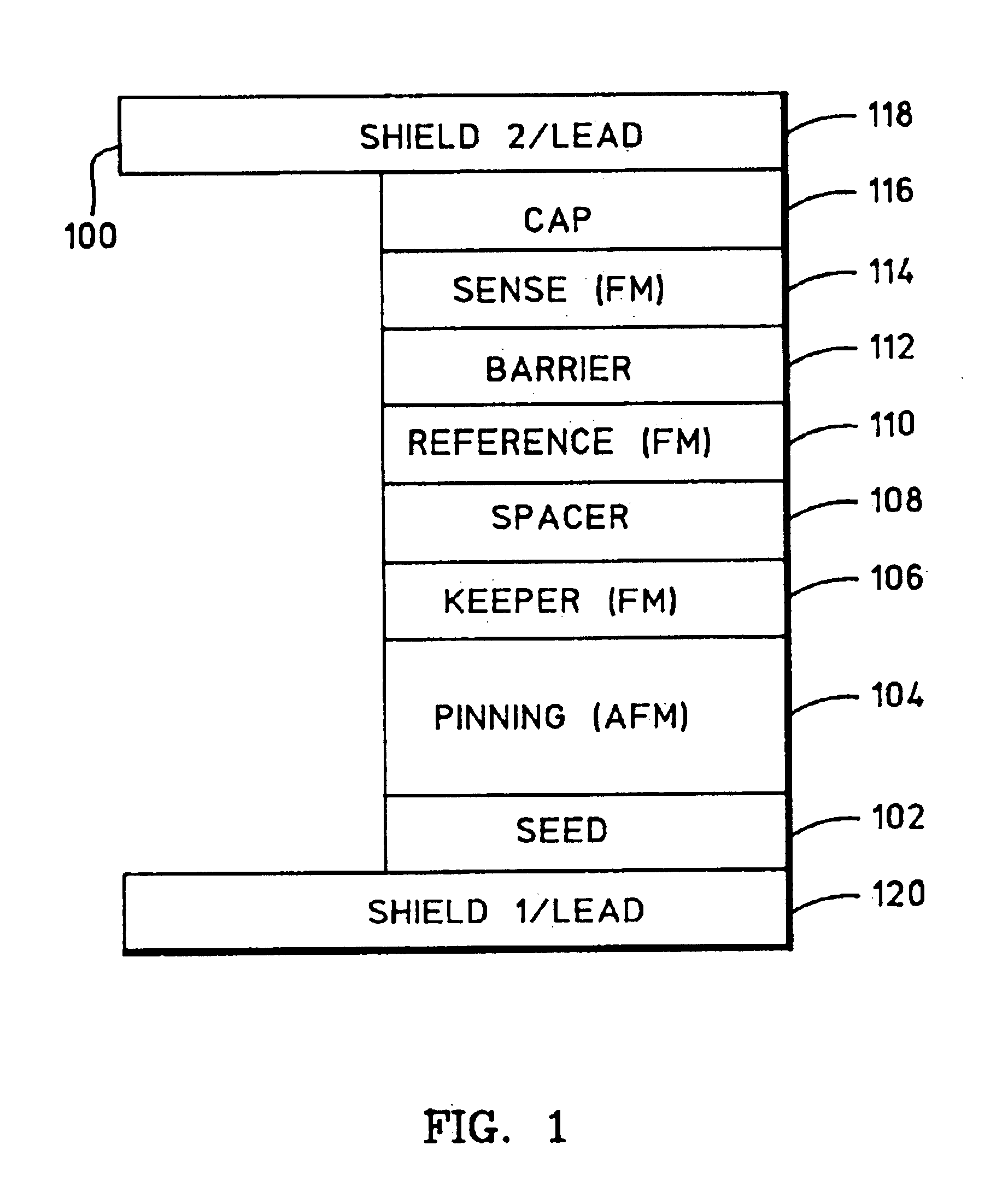
FIG. 4 is a flowchart which describes a method of forming a barrier layer of a tunneling magnetoresistive (TMR) sensor. By making a TMR sensor with a barrier layer in accordance with the method described in relation to FIG. 4, the TMR sensor is provided with good magnetic and TMR properties. A barrier layer is typically formed over and on top of a ferromagnetic (FM) layer, such as the reference layer of a “bottom” TMR sensor comprising seed / pinning / keeper / spacer / reference / barrier / sense / cap layers, as shown in FIG. 1; or the sense layer of a “top” TMR sensor comprising seed / sense / barrier / reference / spacer / keeper / pinning / cap layers. The method of FIG. 4 begins with the formation of the barrier layer over the F...


PUM

PropertyMeasurementUnit
heightaaaaaaaaaa
widthaaaaaaaaaa
easy-axis coercivityaaaaaaaaaa

Abstract

A fabrication process for a tunneling magnetoresistance (TMR) sensor is disclosed. In particular, a unique method of forming a barrier layer of the TMR sensor is utilized so that the TMR sensor exhibits good magnetic and TMR properties. In one particular example, the barrier layer is formed by depositing a metallic film in an argon gas in a DC magnetron sputtering module, depositing an oxygen-doped metallic film in mixed xenon and oxygen gases in an ion-beam sputtering module, and oxidizing these films in an oxygen gas in an oxygen treatment module. This three-step barrier layer formation process minimizes oxygen penetration into ferromagnetic (FM) sense and pinned layers of the TMR sensor and optimally controls oxygen doping into the barrier layer. As a result, the FM sense and pinned layers exhibit controlled magnetic properties, the barrier layer provides a low junction resistance-area product, and the TMR sensor exhibits a high TMR coefficient.

Description

BACKGROUND OF THE INVENTION1. Field of the InventionThis invention relates generally to a tunneling magnetoresistive (TMR) sensor and methods of making the same, and more particularly relates to a method of forming a barrier layer of the TMR sensor which includes a three-step barrier-layer formation process.2. Description of the Related ArtFIG. 1 is a cross-sectional illustration of a tunneling magnetoresistive (TMR) sensor 100. TMR sensor 100 may include a tantalum (Ta) seed layer 102, an antiferromagnetic (AFM) platinum-manganese (Pt—Mn) pinning layer 104, a ferromagnetic (FM) cobalt-iron (Co—Fe) keeper layer 106, a ruthenium (Ru) spacer layer 108, an FM cobalt-iron (Co—Fe) reference layer 110, an insulating aluminum-oxide (Al—O) barrier layer 112, FM cobalt-iron / nickel-iron (Co—Fe / Ni—Fe) sense layers 114, and copper / tantalum (Cu / Ta) cap layers 116. Sense layers 114 may be referred to as free layers, and keeper and reference layers 106 and 110 may be referred to as first and secon...

Claims


Application Information

Patent Timeline
Patent Type & Authority Patents(United States)
IPC IPC(8): G01R33/06H01F41/30H01F10/00H01F10/32H01F41/14G11B5/39H01L43/00H01L43/08H01L43/12H01F41/18G11B5/40G11B5/31
CPCB82Y10/00B82Y25/00B82Y40/00G01R33/06G11B5/3903H01L43/12H01F10/3254H01F41/303H01L43/08G11B5/3909G11B5/3163G11B5/40H01F10/3268H01F41/18H10N50/01H10N50/10
Inventor LINN, TSANNMAURI, DANIELE
Owner GLOBALFOUNDRIES INC
Why Eureka
Try Eureka